
This Arduino ADC tutorial provides a clear and beginner-friendly explanation of how to read analog signals using the analogRead() function. It covers the basics of Analog-to-Digital Conversion, voltage reference, and resolution. With practical code examples, this guide helps you easily interface any analog sensors with your Arduino board using Arduino IDE. Perfect for anyone looking to improve their Arduino skills.
What is ADC?
An ADC (Analog-to-Digital Converter) is a device that converts analog signals into digital signals. Analog signals surround our world. They are continuous and change over time, such as temperature, pressure, and alternating current (AC). However, microcontrollers and computers can only process digital signals, which consist of 1s and 0s. An ADC converts analog signals into digital signals that microcontrollers can process.
How does an ADC work?
ADC converts an analog signal to a digital signal in 3 steps. The 3 steps are –
- Sampling
- Quantization
- Encoding
Sampling
ADC takes samples from the input analog signal at regular intervals in this step. We can understand this process by the given figure below:

Figure 01: Analog signal.
Let’s assume ADC has to sample this analog signal given in Figure 01. The ADC will measure the voltages of the signal after a specific interval of time, as shown in Figure 02.
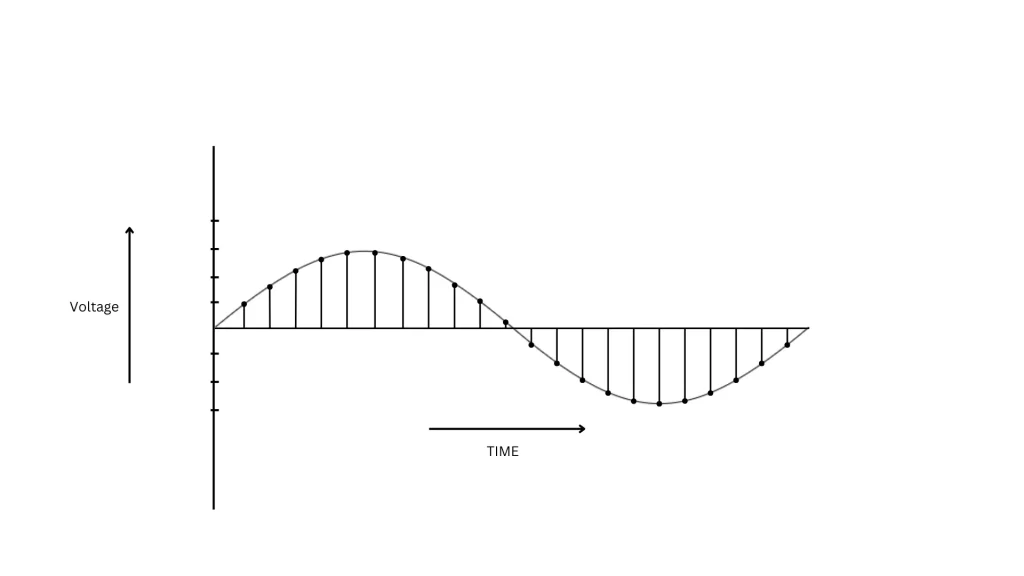
Figure 02: Sampling process
We can say these voltages are taken at regular intervals as samples. How many samples can be taken per second is one of the important things for an ADC. That is where the term sampling rate comes from.
Sampling rate: The sampling rate, also known as the sampling frequency, is the number of samples taken per second in converting an analog signal to digital form.
The sampling rate has a unit of S/s (samples per second) or Hz (if measured in terms of frequency).
The higher the sampling rate, the more accurately an ADC can capture an analog signal. An ADC with a lower sampling rate cannot capture the changes in the analog signal accurately. According to Nyquist’s Theorem, the sampling rate must be more than twice the highest frequency of the signal.
The speed of the ADC also depends on the sampling rate.
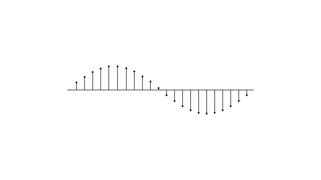
Figure 03: After sampling
Quantization
In this process, each sampled continuous amplitude is rounded to the nearest amplitude and turned into discrete values. We can understand this process by figure-04 :
Figure 04: Quantisation process
Now, the value of each step is determined by the resolution of the ADC.
Resolution: The resolution of ADC is the number of bits it uses to convert an input analog signal into a digital signal. The resolution of an ADC is equal to 2n, where n is the number of bits an ADC can handle.
More resolution means more precision, and a quantised value will be more accurate.
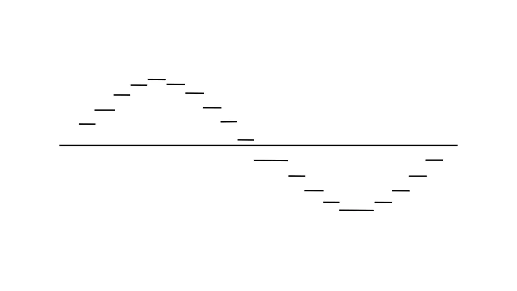
Figure 05: After quantisation
Encoding
The encoder converts the quantised value into binary code.
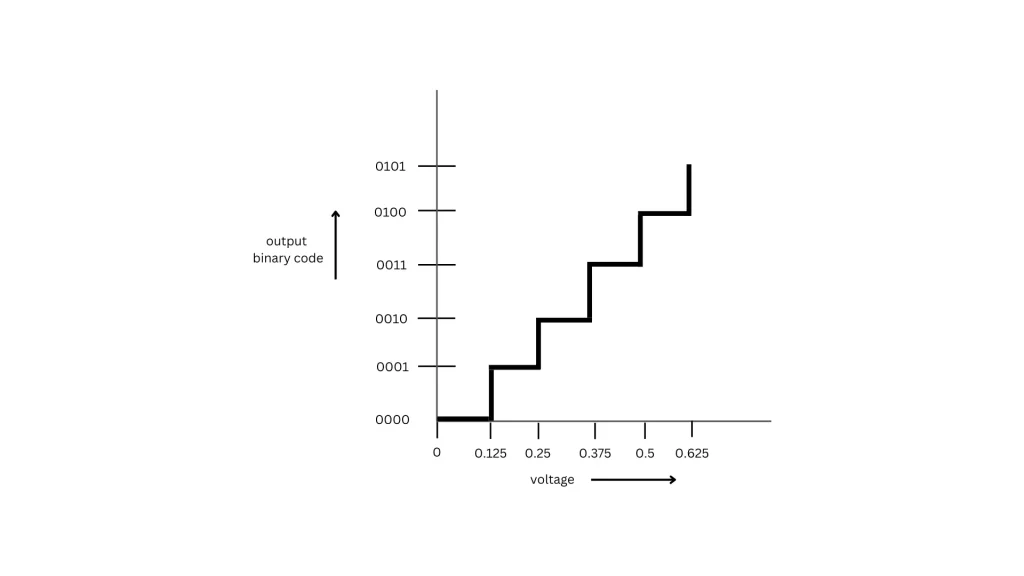
Figure 06: Encoding method
In Figure 06, how a 4-bit ADC encodes a digital signal is shown. In this example, 2V signal is divided into 24 = 16 steps, and each step is 0.125v.
ADC classifications
ADCs are classified based on their specification, like speed, resolution, and power consumption. Depending on their specification, they can be classified into 5 types.
- Successive Aproximation(SAR)
- Delta Sigma
- Flash
- Dual slope
- Pipelined
Successive Approximation Register (SAR) ADC
A Successive Approximation Register (SAR) ADC employs a binary search algorithm. It turns the supplied voltage into a binary value. Then, a digital-to-analog converter (DAC) generates a reference voltage, which is compared to the input voltage using a comparator. The comparison starts from the MSB and proceeds to the LSB. If the input voltage is higher than the reference voltage, the bit is set to one; otherwise, it is set to zero. This procedure continues until it reaches the LSB. The speed of SAR depends on the resolution. It is power-efficient for its circuit design. SAR is frequently applied in industrial control, medical devices, and data acquisition systems.
Delta Sigma ADC
To achieve high accuracy, A Delta-Sigma ADC employs an oversampling technique. The delta sigma ADC consists of an integrator, a comparator, and a flip-flop.
Delta sigma ADCs are widely used in audio equipment, industrial control, and precision sensors.
Flash ADC
A Flash ADC is the fastest type of ADC compared to other designs. It uses a voltage ladder to generate reference voltages and then uses a comparator to compare them with the input voltage. The comparator outputs are then processed by a digital encoder.
Flash ADCS need a comparator for conversion. Making them costly and power-hungry for higher resolutions. Flash ADC are widely used in oscilloscopes, radar systems, and RF communication technologies such as 5G and satellite communications.
Dual Slope ADC
Dual-Slope ADC employs integrators to compare the input voltage Vin to the reference voltage Vref. It measures the input voltage in two phases. The ADC charges an integrator’s capacitor using the input voltage for a specified amount of time T1. Second, an opposite-polarity reference voltage Vref is applied to the integrator. The time T2 required for the integrator’s output to return to zero is measured. Using T1 and T2, the ADC calculates Vin.
This method takes time but is quite accurate. It effectively reduces noise from the input signal. Due to its precision, Dual-Slope ADCs are commonly used in digital multimeters and other applications where accuracy is critical.
Pipelined ADC
A Pipeline ADC offers high speed and resolution. It has multiple stages, where each stage processes a different portion of the analog signal independently and simultaneously. The resolution of the pipeline ADC can be increased by adding more stages because it gives an output by adding all outputs given by the stages.
However, adding more stages increases power consumption and introduces latency, which can be a drawback. Due to its speed and accuracy, Pipeline ADCs are widely used in cameras, medical devices, communication systems, and radar applications.
ADC in Arduino
Arduino’s microcontroller ATmega328P includes a 10-bit successive approximation ADC, which means it transforms input values between 0 and 1023. It can measure voltage from 0V to 5V.If the signal is 0V, the decimal value is 0, whereas if the voltage is 5V, the decimal value is 1023. Arduino has 6 analog input pins for ADC (from A0 to A5).
Measure analog Voltage
Arduino has a library function, analogRead(), to read analog voltages.
Function description
Syntax
analogRead(pin)
Parameters
pin: Number of the analog pin (from A0 to A5).
Returns
Decimal values from 0 to 1023 (for Arduino Uno R3).
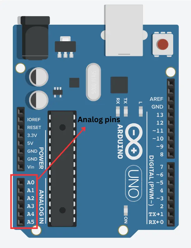
Figure 07: Arduino Uno board
The project: Interfacing the ADC sensor with Arduino
In this project, we will use an Arduino ADC to measure the intensity of light and depending on the light, we will control an LED. If the light in the room is turned on, the green LED turns on and the red LED turns off; if the light is turned off, the red LED turns on and the green LED turns off.
Required Components
| Component Name | Quantity | Purchase Link |
| Arduino Uno R3 | 1 | Amazon |
| photoresistor | 1 | Amazon |
| Resistor pack | 1 | Amazon |
| LED | 1 | Amazon |
| Jumper wire pack | 1 | Amazon |
| Breadboard | 1 | Amazon |
Circuit Diagram
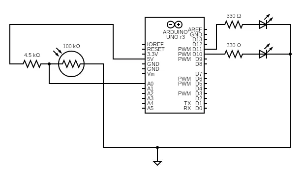
Figure 08: Circuit Diagram
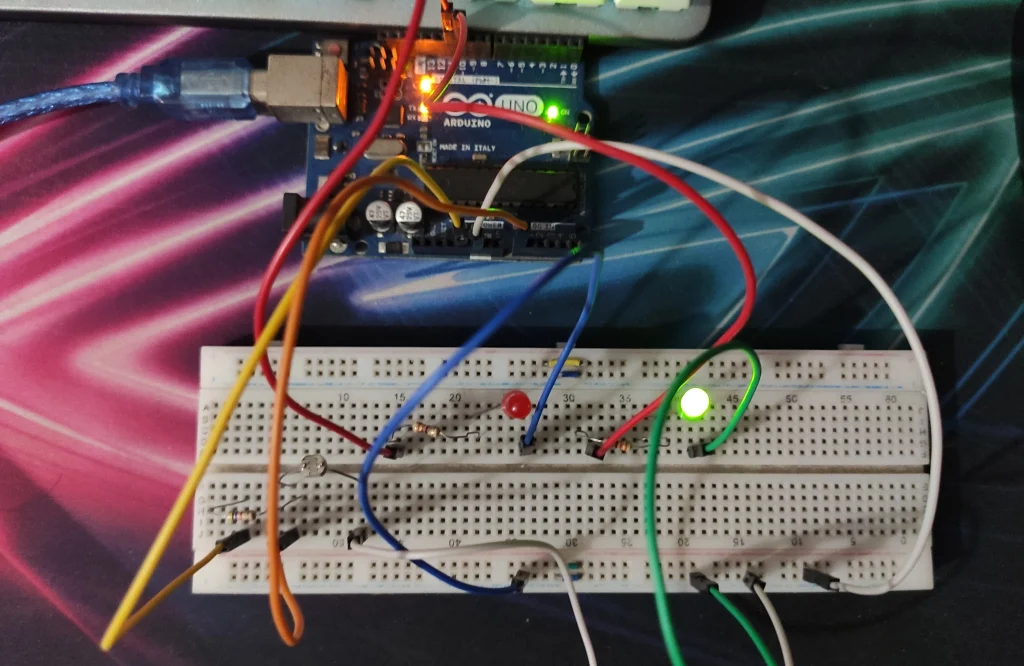
Figure 09: Arduino ADC project
Arduino IDE Code
int digital_pin1 = 10; // Green LED on digital pin 10
int digital_pin2 = 11; //Red LED on digital pin 11
int analog_pin = A0; // analog pin A0
int adc_output; // Store the output of ADC between the range (0 - 1023)
int min_light = 1020; //value of min_light measured in dark room by Serial monitor
void setup() {
  pinMode(digital_pin1, OUTPUT); //Set digital pin 10 as output;

  pinMode(digital_pin2, OUTPUT); //Set digital pin 11 as output;

  pinMode(analog_pin, INPUT); //Set analog pin A0 as output;

  Serial.begin(9600); // opens Serial monitor

}

void loop() {
  adc_output = analogRead(analog_pin); //  Read sensor (0–1023)
  Serial.println(adc_output); // Print the value of variable adc_output

  if(adc_output < min_light)
  {
    digitalWrite(digital_pin1, HIGH); //Turn ON the Green LED
    digitalWrite(digital_pin2, LOW); //Turn OFF the Red LED
  }

  if(adc_output > min_light)
  {
    digitalWrite(digital_pin2, HIGH); //Turn ON the Red LED
    digitalWrite(digital_pin1, LOW); //Turn OFF the Green LED
  }
  delay(100); //Wait 100ms between readings

}
Code explanation
Variable Declarations
int digital_pin1 = 10; // Green LED on digital pin 10
int digital_pin2 = 11; //Red LED on digital pin 11
int analog_pin = A0; // analog pin A0
int adc_output; // Store the output of ADC between the range (0 - 1023)
int min_light = 1020; //value of min_light measured in dark room by Serial monitor
- digital_pin1 and digital_pin2 control the Green (pin 10) and Red (pin 11) LEDS.
- analog_pin variable stores voltages based on the resistance of the photoresistor connected to pin A0.
- The adc_output variable stores the analog value (0–1023) from the sensor.
- min_light variable stores the threshold value for detecting darkness. If the sensor value reaches this, the room is considered “dark.”
Setup() Function
void setup() {
  pinMode(digital_pin1, OUTPUT); //Set digital pin 10 as output;

  pinMode(digital_pin2, OUTPUT); //Set digital pin 11 as output;

  pinMode(analog_pin, INPUT); //Set analog pin A0 as output;

  Serial.begin(9600); // opens Serial monitor


}
- Sets the digital pin 10 and digital pin 11 as outputs.
- Configures analog pin (A0) as an input.
- Sets the Serial Monitor at 9600 baud to display sensor values.
Loop() Function
A. Reading and printing the value from the ADC
void loop() {
    adc_output = analogRead(analog_pin);  Read sensor (0–1023)

  Serial.println(adc_output); // Print the value of variable adc_output
 ...
}
- analogRead(analog_pin) reads the analog voltage at pin A0.
- Bright Light: Sensor value is low.
- Darkness: Sensor value is high.
B. Conditional statement
 if(adc_output < min_light)
  {
    digitalWrite(digital_pin1, HIGH); //Turn ON the Green LED
    digitalWrite(digital_pin2, LOW); //Turn OFF the Red LED
  }

  if(adc_output > min_light)
  {
    digitalWrite(digital_pin2, HIGH); //Turn ON the Red LED
    digitalWrite(digital_pin1, LOW); //Turn OFF the Green LED
  }
- Logic:
- Bright Environment (adc_output < min_light):
- Green LED turns ON.
- Red LED turns OFF.
- Dark Environment (adc_output > min_light):
- Red LED turns ON.
- Green LED turns OFF.
- Bright Environment (adc_output < min_light):
C. Delay
delay(100); // Wait 100ms between readings
- Adds a short delay to stabilise readings and reduce flickering.
Note: The resistor in series with the photoresistor can be greater than 4.5kΩ but less than or equal to 10kΩ.