
In this project, I built a compact mini drone using an ESP32 microcontroller, a custom-designed PCB, an MPU6050 sensor, four coreless motors, and an Android-based remote-control app. The main goal was to make a low-cost, lightweight, and fully programmable drone that can be modified and improved through software.
Building a drone from scratch is a challenging but exciting electronics project. A drone combines mechanical design, PCB design, embedded programming, sensor data processing, motor control, wireless communication, and power management in one complete system.
This guide explains the full building process step by step, from component selection to final assembly and software setup.
The complete code and PCB schematic are available in the GitHub repository:
https://github.com/saumik02/ESP32_MINI_DRONE
Step 1: Understanding the Project Goal
The goal of this project was to build a mini quadcopter that is:
- Small and lightweight
- Low cost
- Fully programmable
- Controlled using ESP32 Wi-Fi
- Built with a custom PCB
- Suitable for learning drone electronics and flight control
Instead of using a ready-made flight controller, I designed a custom ESP32-based controller. This makes the project more educational because every part of the drone, including motor control, sensor reading, calibration, and PID tuning, can be understood and modified.
Step 2: Collecting the Main Components
Before starting the build, the required components must be collected. The drone has two main hardware parts:
- The flight controller PCB components.
- The external drone components.
Flight Controller Components:
| Component | Quantity | Purpose | Purchase Link |
|---|---|---|---|
| ESP32 38-pin module | 1 | Main controller and Wi-Fi communication | Amazon | AliExpress |
| MPU6050 | 1 | Gyroscope and accelerometer sensor | Amazon | AliExpress |
| AO3400N MOSFET | 8 | Motor driving circuit | Amazon | AliExpress |
| 100-ohm SMD resistor | 6 | Supporting circuit | Amazon | AliExpress |
| 10k SMD resistor | 6 | Pull-up or pull-down support | Amazon | AliExpress |
| 1 µF SMD capacitor | 6 | Filtering and stability | Amazon | AliExpress |
| 1N4148 SMD diode | 4 | Protection and signal support | Amazon | AliExpress |
| SMD LED | 4 | Status indication | Amazon | AliExpress |
| DD38LOSA 3.3V DC-DC / LDO Module | 1 | Voltage regulation | Amazon | AliExpress |
| JST connector | 4 | Motor and battery connection | Amazon | AliExpress |
External Components:
| Component | Quantity | Purpose | Purchase Link |
|---|---|---|---|
| 1020 coreless motor | 4 | Provides thrust | Amazon | AliExpress |
| 76 mm propellers (2 pair) | 4 | Generates lift | Amazon | AliExpress |
| Drone frame | 1 | Holds all components | Amazon | AliExpress |
| 1S Li-Po battery, 80C, 300 mAh | 1 | Main power source | Amazon | AliExpress |
| Custom PCB | 1 | Flight controller board | Amazon | AliExpress |
| Drone frame | 1 | Mechanical structure of the mini drone | Amazon | AliExpress |
Step 3: Designing the Schematic
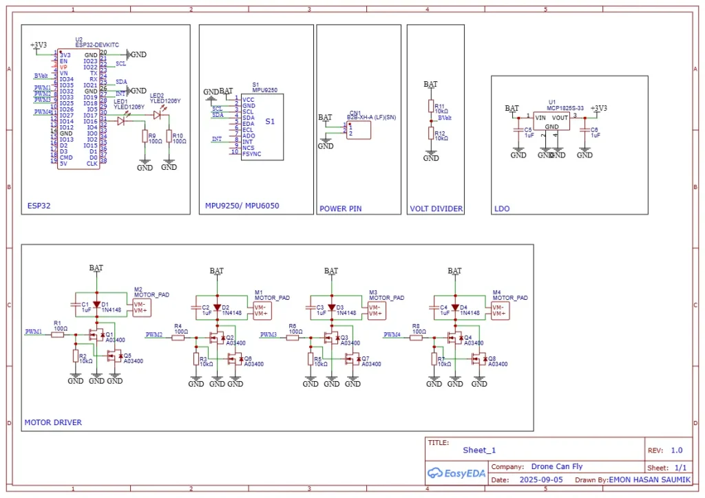
Overall Working
When the battery is connected, the BAT line powers the motor driver circuit and the LDO regulator. The LDO generates 3.3V for the ESP32 and MPU sensor.
The ESP32 reads drone angle data from the MPU sensor using SDA and SCL. It also reads battery voltage through the BVolt pin. After processing the sensor data and control input, the ESP32 sends PWM1 to PWM4 signals to the motor drivers. The motor drivers then control the speed of the four motors and help the drone fly and balance.
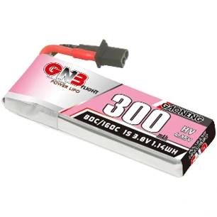
Step 4: Choosing the Correct Battery
Battery selection is one of the most important parts of this project. The drone uses four small DC motors, and these motors can draw high current during operation.
If the battery cannot supply enough current, the ESP32 may reset again and again. This happens because the voltage drops when the motors suddenly demand high current.
For this drone, I used a 1S 300 mAh Li-Po battery with an 80C rating. C rating is basically the discharge rate of the battery.
The maximum current capacity can be estimated like this:
300 mAh = 0.3 Ah
0.3 × 80C = 24 A
So, this battery can theoretically deliver up to 24 A, which is suitable for this mini drone. It is also lightweight, which helps improve flight performance.
Step 5: Assembling the PCB
After receiving the PCB, the components must be soldered carefully.
The recommended assembly process is:
- Solder the small SMD resistors and capacitors first.
- Solder the diodes and LEDs.
- Solder the MOSFETs.
- Solder the LDO regulator.
- Mount the ESP32 module.
- Mount the MPU6050 sensor.
- Solder the JST connectors for motors and battery.
- Check all solder joints carefully.
- Use a multimeter to check for short circuits before connecting the battery.
This step must be done carefully because a small soldering mistake can damage the ESP32, sensor, or battery.
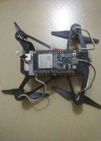
Step 6: Mounting the PCB on the Frame
After assembling the PCB, the board is mounted on the drone frame. The PCB should be placed near the center of the frame to keep the drone balanced.
A balanced frame is very important because if one side is heavier than the other, the drone will need more correction from the motors. This can reduce stability and flight time.
The battery should also be placed near the center of gravity. The wires should be kept short and properly fixed so they do not touch the propellers during flight.
The frame is the main body of the drone, so it must be lightweight, balanced, and strong enough to hold the motors, PCB, battery, and propellers. For this mini drone, a small quadcopter-style frame was used with four arms for mounting the 1020 coreless motors.
To make this type of frame, first design the frame in any CAD software such as Fusion 360, SolidWorks, or Tinkercad. The design should have four equal-length arms so that all motors stay at the same distance from the center. At the end of each arm, make a circular motor holder where the 1020 coreless motor can fit tightly.
The center part of the frame should have enough space to mount the flight controller PCB, ESP32, MPU6050, and battery. Try to keep the center area compact but strong, because this part carries most of the weight. The frame should also have open spaces or cutouts to reduce extra weight.
After completing the design, the frame can be made using a 3D printer. PLA can be used for simple testing, but PETG or ABS is better if more strength is needed. After printing, check that all four motors fit properly and that the frame is not bent. Finally, mount the motors, PCB, and battery in the center position so the drone stays balanced during flight.
In this project, the frame was designed to keep the drone small and lightweight. This helps the coreless motors lift the drone more easily and improves flight stability.
Step 7: Connecting the Motors
The drone uses four motors. Each motor must be connected to the correct ESP32 output pin and must rotate in the correct direction.
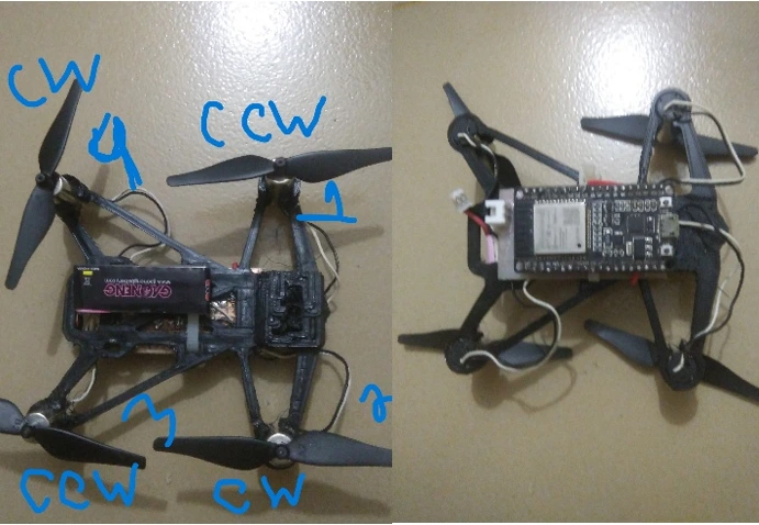
| ESP32 Pin | Motor Position | Rotation Direction |
|---|---|---|
| GPIO 27 | 1 (Front right) | CCW (Counterclockwise) |
| GPIO 25 | 2 (Rear right) | CW (Clockwise) |
| GPIO 33 | 3 (Rear left) | CCW (Counterclockwise) |
| GPIO 32 | 4 (Front left) | CW (Clockwise) |
This motor direction is very important. In a quadcopter, two motors rotate clockwise and two motors rotate counterclockwise. This balances the torque and helps the drone stay stable.
If the motor direction or propeller direction is wrong, the drone may flip over during takeoff.
Step 8: Checking the MPU6050 Orientation
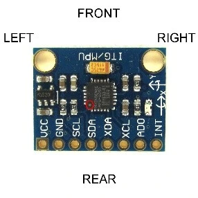
The MPU6050 sensor measures the drone’s angle and movement. The flight controller uses this data to stabilize the drone.
The orientation of the MPU6050 must be correct. In this project, the dot on the MPU6050 should point toward the left rear side of the drone.
If the sensor is mounted in the wrong direction, the controller will read incorrect angle data. As a result, the drone may become unstable or flip immediately after takeoff.
Step 9: Uploading the ESP32 Code
After completing the hardware setup, the next step is uploading the software.
To upload the code:
- Download the code from the GitHub repository.
- Open the code in Arduino IDE.
- Install ESP32 board support in Arduino IDE.
- Select the correct ESP32 board.
- Select the correct COM port.
- Connect the ESP32 using USB.
- Upload the code.
For better stability, tweak these parameters in the code:
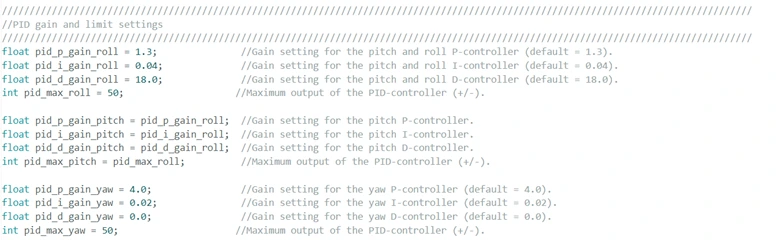
After uploading the code successfully, disconnect the USB and prepare the drone for calibration.
Step 10: Installing the Android Remote App
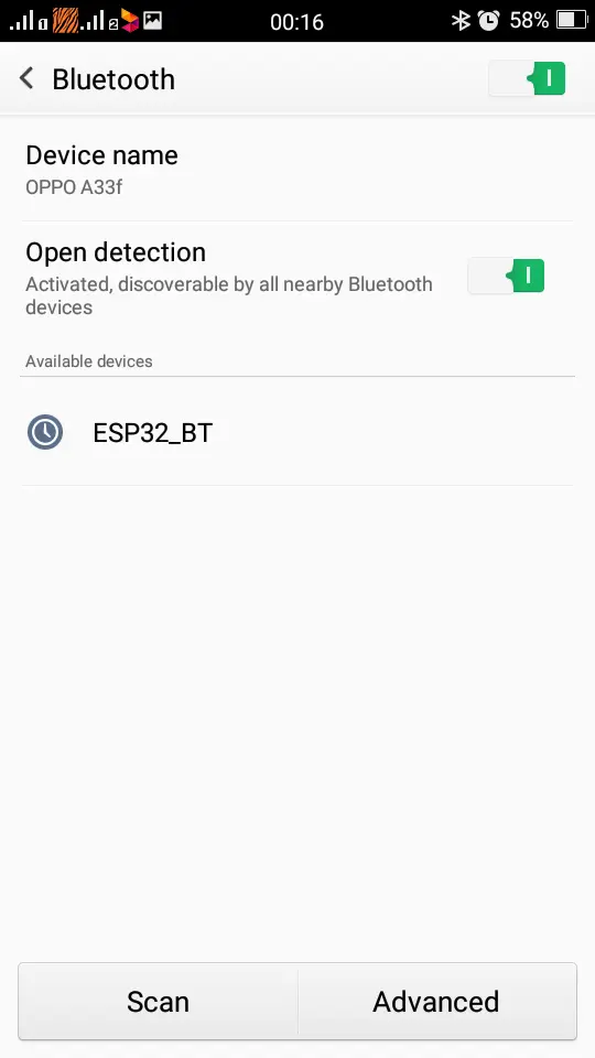
The drone is controlled using an Android remote-control app. The APK file is available in the project repository.
To set up the remote:
- Download the APK file.
- Install it on an Android phone.
- Power on the drone.
- Wait for the ESP32 Wi-Fi hotspot to appear.
- Connect to the hotspot named drony.
- Use the password 11223344.
- Open the remote app.
- Click Pair.
- Click ARM.
- The drone is ready for testing.
Step 11: Calibration Before Flight
Before flying the drone, calibration is necessary. After connecting the battery, keep the drone on a flat surface and do not move it for around 30 seconds.
During this time, the MPU6050 sensor calibrates its initial position. If the drone is moved during calibration, the sensor offset may become incorrect, and the drone may not fly properly.
Before the first flight, always check:
- Battery is fully charged
- Propellers are installed correctly
- Motors rotate in the correct direction
- ESP32 does not reset when throttle increases
- The drone is placed on a flat surface during calibration
- The remote app is connected properly
Step 12: PID Tuning for Stability
PID tuning is an important part of drone development. PID control helps the drone correct its angle and stay balanced in the air.
If the PID values are not correct, the drone may:
- Shake too much
- Respond slowly
- Flip during takeoff
- Drift to one side
- Become difficult to control
The PID values can be adjusted in the ESP32 code. Start with small changes and test carefully. For safety, test the drone at low throttle first before attempting a full flight.
Step 12: First Flight Test
For the first test flight, choose an open and safe area. Do not test near people, pets, glass, or fragile objects.
During the first flight:
- Place the drone on a flat surface.
- Connect the battery.
- Wait for calibration.
- Connect the phone to the ESP32 Wi-Fi.
- Open the app and pair the drone.
- Arm the drone.
- Slowly increase the throttle.
- Observe if the drone lifts evenly.
- If it flips, immediately stop and check motor direction, propeller direction, and MPU6050 orientation.
- If it shakes, adjust the PID values.
The first few tests are usually for checking balance, motor response, and control stability.
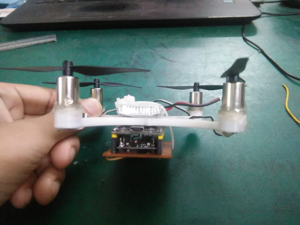
Final Result
After completing the PCB assembly, motor connection, software upload, calibration, and PID tuning, the final drone became a compact ESP32-based mini quadcopter. It is lightweight, programmable, and controlled wirelessly using an Android app.
This project is a great learning platform for anyone interested in drones, robotics, embedded systems, and PCB design. It shows how a complete drone can be built from scratch using affordable components and open-source tools.