The ESP32 is one of the most powerful microcontrollers with its 32-bit dual-core system. It’s become popular for Wi-Fi and Bluetooth features with a maximum 12-bit ADC and 160 MHz frequency. On the other hand, UART (Universal Asynchronous Receiver-Transmitter) is the simplest form of serial communication protocol with its point-to-point connection. In this tutorial, you’ll discover how to get started with UART with ESP32, explore its key features, and learn how to use it for real-world applications.
Serial Port (UART) on ESP32
UART shows its fundamental behavior when transmitting data from the ESP32 to another microcontroller. A two-wire system is used here; one is Tx, which acts as a transmission line, while Rx is the receiving line. UART, the serial communication device, transfers and receives data bit by bit (mostly 8-bit data, including start and stop bit data frames).
The UART communication protocol is named after an Asynchronous receiver transmitter, which means this protocol allows asynchronous (not synchronous) transmission and reception of data between two devices with full duplex compatibility.
Actually, UART lets those devices communicate and transmit data without the same operating frequency (unlike synchronous communications, such as SPI or I2C), which is considered the main advantage of this communication protocol. For instance, two microcontrollers operating at different clock frequencies can communicate and transmit data between them easily via serial communication.

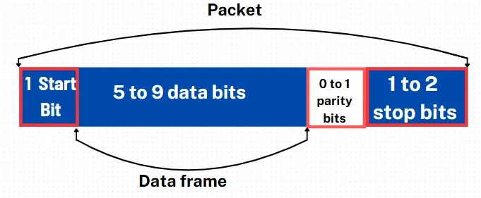
Data frame
Instead of clock signals, UART relies on start and stop bits to indicate the beginning and end of the data, enabling the receiver to know when to begin and finish reading. The receiving UART accepts the start bit and begins reading the incoming bits at a particular rate known as the baud rate (bps). For successful communication, both UARTs require nearly the same baud rates, with a difference of no more than 10%. They must also be configured to recognize the same data formats. Optionally, a Parity Bit (1 bit) may be included for basic error checking, ensuring data integrity during transmission.

ESP32 UART Pins
The ESP32 has 3 UARTs, such as UART0, UART1, and UART2. Though the Arduino environment only uses RX and TX, in the ESP32 we can use four pins: RX, TX, CTS, and RTS. However, we can reassign the UART to any pin without loss of performance for its multiplexer. The UARTs come preconfigured to use certain pins, but sometimes we have to change them depending on the demand of projects.
| UART Port | TX | RX | RTS | CTS |
| UART0 | 1 | 3 | 22 | 19 |
| UART1 | 10 | 9 | 11 | 6 |
| UART2 | 17 | 16 | 7 | 8 |
Esp32 UART Usages and advantages
Data exchange: UART communication protocol in ESP32 assists in exchanging data with other microcontrollers (e.g., Arduino, STM32).
Peripheral Communicator: easily communicate with peripheral like actuators or modules like GSM/LTE modules (e.g., SIM800L, u-blox SARA-R4) and GPS modules (e.g., Neo-6M).
Full-Duplex Communication: Simultaneous transmission and reception of data.
Interrupt Handling: ESP32 provides robust interrupt-driven UART communication.
DMA Support: UART communication can use DMA (Direct Memory Access) for efficient data transfer without CPU involvement.
Example of Esp32 UART
In this example, we will delve into the workings of ESP32 UART communication by transmitting data to another microcontroller device. For simplicity, we will discuss a simple project for better understanding.
Required Components
| Component Name | Quantity | Purchase Link |
|---|---|---|
| ESP32 development board | 1 | Amazon |
| Arduino Uno | 1 | Amazon |
| Connecting wire pack | 1 | Amazon |
| Breadboard | 2 | Amazon |
Affiliate Disclosure: When you click on links to make a purchase, this can result in this website earning a commission.
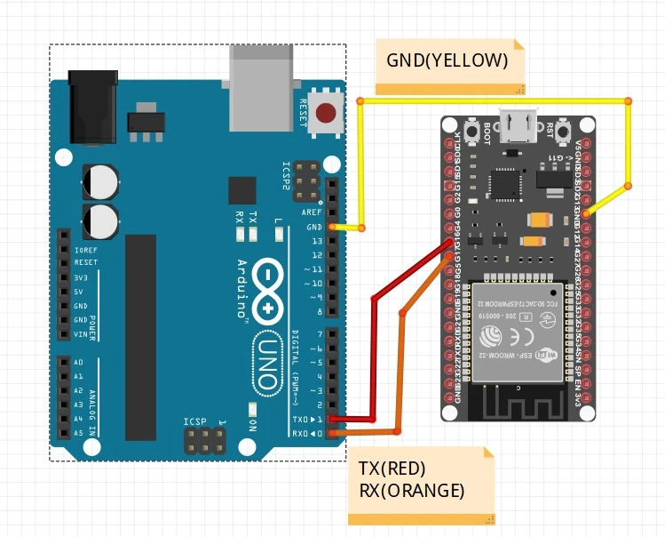
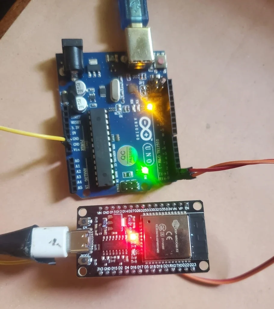
Connection Diagram

We have declared TX of ESP32 connected with RX of Arduino and also, declared RX of ESP32 connected with TX of Arduino. Also, make sure both microcontroller boards have their grounds in common.

Arduino Sketch
Open your Arduino IDE and go to File > New to open a new file. Copy the code given below and save it.
void setup() {
  Serial.begin(9600);
}
void loop() {
  Serial.println("embeddedthere");
  delay(1500);
How the Code Works
After the execution of the code, setup () function runs once when the Arduino starts up or is reset. And initializes the serial communication with a baud rate of 9600 bits per second. These 9600 bits per second mean the number of bits (9600 bits) will be transmitted through the communication channel in one second.
void setup() {
  Serial.begin(9600);
}
The loop function works constantly after the execution of the setup() function. And with the help of the Serial.println function, we can send the string “embeddedthere” through the serial port, which will be received by the ESP32’s UART. After that, the delay(1500) function will pause the code execution for 1,500 milliseconds (1.5 seconds) before repeating the loop.
void loop() {
  Serial.println("embeddedthere");
  delay(1500);
}
ESP32Sketch
Open your Arduino IDE again and go to File > New to open a new file with a different name (ex. esp32_ receiver) Copy the code given below and save it.
#define RXp2 16
#define TXp2 17
void setup() {
  // put your setup code here, to run once:
  Serial.begin(115200);
  Serial2.begin(9600, SERIAL_8N1, RXp2, TXp2);
}
void loop() {
    Serial.println("Message Received: ");
    Serial.println(Serial2.readString());
}
How does the Code Work?
Before executing the setup function, declare the Rx and Tx pins for UART2 with the advantages of the multiplexer of the ESP32.
#define RXp2 16
#define TXp2 17
In the setup function, for communicating with the host (PC, laptop), initialize the default UART0 via the baud rate of 11500 bps (bits per second). Moreover, the Serial2.begin function assists us in communicating at a rate of 9600 bps with other microcontrollers. Configured SERIAL_8N1 for UART communication at 8 data bits with a parity bit (N) to detect errors and one stop bit. Pins 16 (RX) and 17 (TX) are used for UART2 communication. Configured as RXp2 and TXp2.
void setup() {
  Serial.begin(115200);
  Serial2.begin(9600, SERIAL_8N1, RXp2, TXp2);
In the loop function, UART (serial) sends a debug message to the host (PC, laptop). This message will be displayed in the serial monitor with a baud rate of 11500 bps. Now, the serial2.readString() function reads incoming data from UART2 (Serial2) as a string. Check if any data is received on UART2. If data is received, it reads the string and sends it to the Serial Monitor.
void loop() {
    Serial.println("Message Received: ");
    Serial.println(Serial2.readString());
Final result
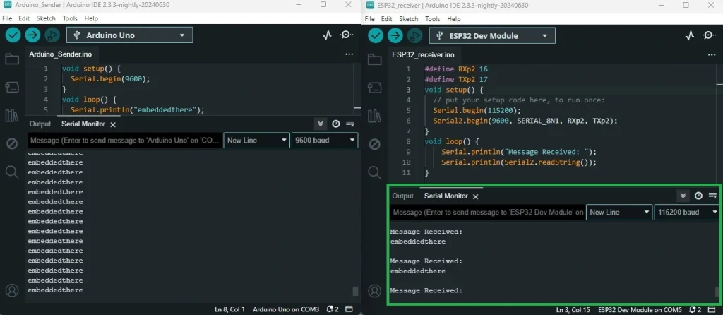
After execution and sending data through UART (serial) from a microcontroller, we can see the result where data is successfully received as “embedded there” in the form of a string with the help of ESP32 UART. We have used one IDE for this experiment.

Conclusion
Nowadays, ESP32 UART communication offers lots of facelifts with its serial communication protocol system in the field of IoT and embedded systems. Conscious message: Before uploading the code from a PC or laptop in your Arduino, never forget to remove the Rx and Tx pins if you don’t want to fry your Arduino 😊.
