
Flip-flop is one of the most important topics for making memory devices and digital logic circuits. In this article, I will discuss the basics of Flip Flop, types of Flip Flop with logic diagrams and truth tables, the workings of Flip Flop, and their applications.
You may also like reading:
Introduction of Flip-Flops
Flip flops are fundamental building blocks of digital circuitry that play a pivotal role in storing and transmitting binary information. It operates with two stable states, often referred to as “set” and “reset,” which determine its output. Flip flops play a vital role in sequential logic circuits, memory elements, and counters, enabling the storage and manipulation of digital data.
Another digital storing device is latching circuit but they have some difference. Before move into more about Flip-Flop, let’s clarify difference between Flip-Flop and Latching Circuit.
Difference Between Flip-Flop and Latching Circuit
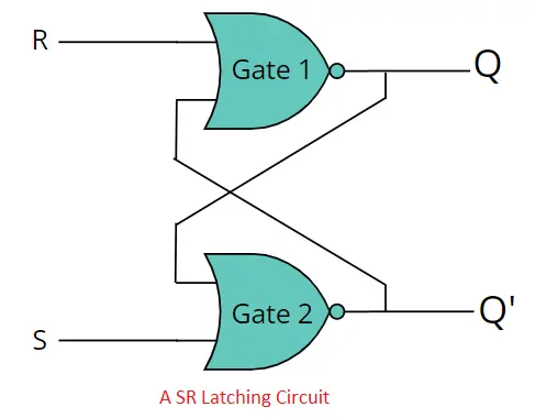
Flip flops and latch circuits are both crucial components in digital electronics, but they differ primarily in their clocking mechanism. Flip flops are edge-triggered, responding to specific transitions of the clock signal, which makes them suitable for sequential circuits. Latch circuits, on the other hand, are level-sensitive, reacting to continuous changes in input signals, making them more suitable for simpler tasks like data storage and temporary signal holding.
Types of Flip-Flop
- SR Flip-Flop
- D Flip-Flop
- JK Flip-Flop
- T Flip-Flop
SR Flip-Flop
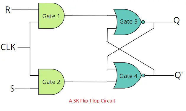
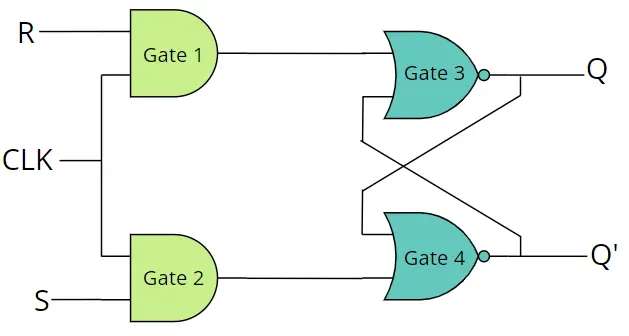
An SR flip-flop, also known as a Set-Reset flip-flop, is a fundamental digital circuit element used in digital electronics and sequential logic circuits. The SR flip-flop has two inputs, the Set (S) input and the Reset (R) input, and two complementary outputs, the Q output and the Q̅ (Q-bar) output. A clock signal (CLK) must be need for operating SR flip-flop. The SR flip-flop can be made by AND and NOR or only NAND gates. We make it with AND and NOR gates.
Circuit Diagram
Working Principle of SR Flip-Flop
The SR flip-flop has four possible cases for full operation.
| Case | S | R | Gate 01 | Gate 02 | Gate 03 / Q | Gate 04 / Q’ |
|---|---|---|---|---|---|---|
| 01 | 0 | 0 | 0 | 0 | Q [No change] | Q’ [No change] |
| 02 | 0 | 1 | 1 | 0 | 0 | 1 |
| 03 | 1 | 0 | 0 | 1 | 1 | 0 |
| 04 | 1 | 1 | 1 | 1 | 0 or 1 [INVALID] | 0 or 1 [INVALID] |
Note: From the above table, we can see that the output of the SR flip-flop holds the previous output when both S and R are LOW. If S is set to HIGH, then Q will be HIGH, which means set, and If R is set to HIGH, then Q will be LOW, which means RESET. The most important disadvantage of the SR flip-flop is that when both S and R are high, the output will be 1 or 0, which is impossible and is called an invalid output.
SR Flip-Flop Truth Table
| S | R | Q(t) | Q̅(t) |
|---|---|---|---|
| 0 | 0 | Q(t) [No change] | Q̅(t) [No change |
| 0 | 1 | 0 [RESET] | 1 |
| 1 | 0 | 1 [SET] | 0 |
| 1 | 1 | ?? [INVALID] | ?? [INVALID] |
From the characteristic table of the SR flip-flop, we can find more details about the behavior of the SR flip-flop. From the truth table, we only know the present stage of output, but from the characteristic table, we know the present and next stages of output.
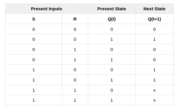
SR Flip-Flop Characteristic Table
From the characteristic table of the SR flip-flop, we can find more details about the behavior of the SR flip-flop. From the truth table, we only know the present stage of output, but from the characteristic table, we know the present and next stages of output.
SR Flip-Flop K-map
By using K-Map we can get the characteristic equation of SR flip-flop.
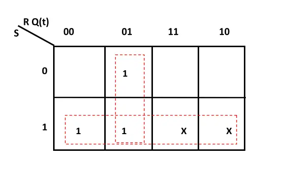
Characteristic Equation of SR flip-flop
Q(t+1) = S + R’Q(t)
Applications of SR Flip-Flop
Latching Circuit: The SR flip-flop can be used as a basic latching circuit to store a single bit of information. For example, it can be used to implement temporary storage in control systems, where the state of a switch or sensor needs to be remembered until the next processing step.
Control Systems: In simple control systems or digital control circuits, SR flip-flops can be used to store control signals that determine the state of the system.
Frequency Division: In some counter circuits or frequency divider applications, an SR flip-flop can be used to divide the input frequency by 2. It helps generate square wave outputs with half the frequency of the input signal.
Temporary Storage: SR flip-flops can be used in scenarios where temporary storage is needed, and the occasional ambiguity resulting from the “forbidden” state (both S and R inputs set) is manageable or irrelevant.Button Debouncing: SR flip-flops can be employed to debounce noisy or erratic signals from mechanical switches or buttons.
However, there is a potential issue with the basic SR flip-flop: when both S and R inputs are activated simultaneously (S = 1, R = 1), it can enter an undefined state, and it’s uncertain whether the Q output will be 0 or 1. To avoid this problem, clocked flip-flops, like the D flip-flop or JK flip-flop, are often used instead, as they have more predictable behavior and are suitable for synchronous systems.
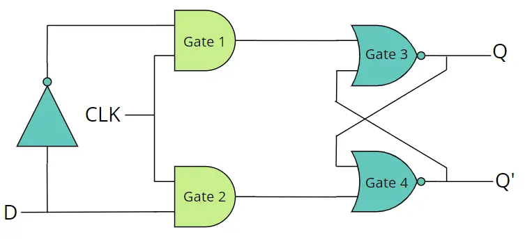
D Flip-Flop
To eliminate the invalid issue of the SR flip-flop, the D flip-flop can be used. A D flip-flop, also known as a Data or Delay flip-flop, is a fundamental building block in digital electronics and sequential logic circuits. It is designed by placing a NOT gate between S and R, and only D is used to operate the D flip-flop. The D flip-flop has only two stages, SET and RESET. These two stages are controlled by data line D (or input).
D Flip-Flop Circuit Diagram
Working Principle of D Flip-Flop
The D flip-flop has two possible cases. We assume the clock signal always HIGH.
| Case | D | CLK | Gate 01 | Gate 02 | Gate 03 / Q | Gate 04 / Q’ |
|---|---|---|---|---|---|---|
| 0 | 1 | 1 | 0 | 0 [RESET] | 1 | |
| 1 | 1 | 1 | 0 | 1 [SET] | 0 |
Note: The D flip-flop only has SET and RESET mode. In SET mode D will be HIGH and in RESET mode D will be LOW.
D Flip-Flop Truth Table
| CLK | D | Q(t+1) |
|---|---|---|
| 1 | 0 | 0 [RESET] |
| 1 | 1 | 1 [SET] |
D Flip-Flop Characteristic Table
From the truth table, we only know the present stage of output, but from the characteristic table, we know the present and next stages of output.
| D | Q(t) | Q(t+1) |
|---|---|---|
| 0 | 0 | 0 |
| 0 | 1 | 0 |
| 1 | 0 | 1 |
| 1 | 1 | 1 |
D Flip-Flop K-map
By using K-Map we can get the characteristic equation of D flip-flop.
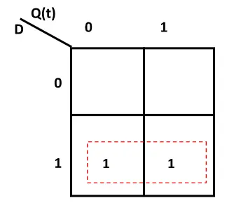
Characteristic Equation of D flip-flop
Q(t+1) = D
Applications of D Flip-Flop
Registers and Memory Elements: D flip-flops are used to build registers and memory elements in digital systems. These registers store data temporarily and are essential for tasks like data buffering, data transfer, and temporary storage within microprocessors and microcontrollers.
Clock Division and Frequency Division: D flip-flops are employed in clock dividers and frequency counters. By repeatedly toggling the flip-flop using a clock signal and measuring the output frequency, they can be used to divide the input clock frequency by a specific factor.
Synchronous Data Transfer: D flip-flops play a significant role in synchronizing data transfers within digital systems.
Edge Detection: D flip-flops can be used to detect edges in digital signals. By comparing the current state of the flip-flop with its previous state, it’s possible to identify rising or falling edges in an input signal, which is useful for tasks like signal conditioning or triggering events based on signal transitions.
Digital Counters: D flip-flops are used in constructing digital counters, such as binary counters or up/down counters.
Shift Registers: D flip-flops are used in shift registers, which are sequential logic circuits capable of storing and shifting data. Shift registers find application in tasks like data serialization, parallel-to-serial conversion, and serial-to-parallel conversion.
State Machines: D flip-flops are integral to constructing finite state machines, which are used to design sequential logic systems. State machines are employed in a wide range of applications, including digital control systems, protocol handling, and automation.
JK Flip-Flop
The JK flip-flop is designed to enhance the functionality of the SR flip-flop by addressing its undefined state. In the SR flip-flop, when both the Set (S) and Reset (R) inputs are active (both 1), it can enter an uncertain state due to the cross-coupling nature of its NAND gates.
To tackle this issue, the JK flip-flop introduces the concept of feedback. This feedback helps eliminate the undefined state by providing a way for the flip-flop to transition from one state to another in a controlled manner.
In terms of circuit implementation, while it’s possible to create JK flip-flops using only NAND gates, let’s consider a circuit that employs both AND and NOR gates, similar to how we discussed the SR flip-flop.
JK Flip-Flop Circuit Diagram
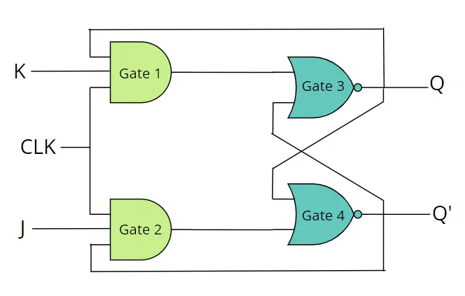
Working Principle of JK Flip-Flop
The JK flip-flop has four possible cases for full operation. We assume the clock signal always HIGH.
| Case | J | K | Gate 01 | Gate 02 | Gate 03 / Q | Gate 04 / Q’ |
|---|---|---|---|---|---|---|
| 01 | 0 | 0 | 0 | 0 | Q [No change] | Q’ [No change] |
| 02 | 0 | 1 | 1 | 0 | 0 [RESET] | 1 |
| 03 | 1 | 0 | 0 | 1 | 1 [SET] | 0 |
| 04 | 1 | 1 | 1 | 1 | Q’ [TOGGLE] | 0 |
Note: From this table, we can see that if J and K are LOW then the JK flip-flop holds the previous stage. The JK flip-flop can be reset by making K as HIGH and set by making J as HIGH. When J and K both are HIGH, then the JK flip-flop toggles the output, which means HIGH to LOW or LOW to HIGH.
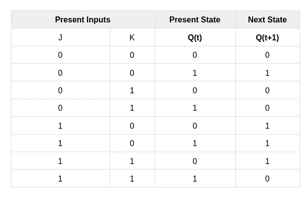
JK Flip-Flop Truth Table
| J | K | Q(t) | Q’(t) |
|---|---|---|---|
| 0 | 0 | Q(t) [No change] | Q’(t) [No change] |
| 0 | 1 | 0 [RESET] | 1 |
| 1 | 0 | 1 [SET] | 0 |
| 1 | Q’ [TOGGLE] | 0 |
JK Flip-Flop Characteristic Table
From the characteristic table of the JK flip-flop, we can find more details about the behavior of the JK flip-flop. From the truth table, we only know the present stage of output, but from the characteristic table, we know the present and next stages of output.
J-K Flip Flop K-map
By using K-Map we can get the characteristic equation of SR flip-flop.
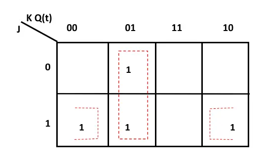
Characteristic Equation of JK flip-flop
Q(t+1) = JQ’(t) + K’Q(t)
Applications of JK Flip-Flop
Counters: JK flip-flops are commonly used in designing various types of counters, including binary counters, decade counters, and up/down counters. They enable the sequential counting of binary values and are crucial components in digital clocks, timers, and frequency dividers.
Shift Registers: JK flip-flops are used in the construction of shift registers, which are used for serial data storage and transfer. Shift registers find applications in tasks like data serialization, parallel-to-serial conversion, and serial-to-parallel conversion.
Memory Elements: JK flip-flops can be used to create memory elements in digital circuits. They form the basis of registers and memory cells, which store and manipulate data in microprocessors and digital systems.
Pulse Generators and Timers: JK flip-flops can be used to design pulse generators and timers in electronic circuits. These are used in applications such as waveform generation, timing signals for various processes, and creating adjustable delays.
Control Logic: In digital systems, JK flip-flops are employed in various control logic circuits, such as toggle circuits, frequency dividers, and conditional execution in microprocessors.
Difference between SR and JK Flip-Flop
Behavior During Set and Reset:
- JK Flip-Flop: The JK flip-flop has a more controlled behavior during both set and reset operations. It can be set or reset based on its inputs, but it also has a toggle (or flip) capability when both inputs are active.
- SR Flip-Flop: The SR flip-flop can be set, reset, or hold its state. However, when both inputs are active (S=1, R=1), it can enter an undefined state due to its cross-coupling nature.
Feedback and Elimination of Undefined State:
- JK Flip-Flop: The JK flip-flop introduces the concept of feedback, which eliminates the undefined state issue present in the SR flip-flop. This feedback ensures that the flip-flop can transition between states in a controlled manner.
- SR Flip-Flop: The SR flip-flop lacks this feedback, leading to the potential for undefined states when both inputs are high, making it less reliable than the JK flip-flop.
Toggle Capability:
- JK Flip-Flop: The JK flip-flop has a unique feature where it can toggle its state when both inputs are active, effectively changing its current state.
- SR Flip-Flop: The SR flip-flop does not inherently have a toggle capability, and its behavior when both inputs are active is not well-defined.
T Flip-Flop
The T flip-flop, also known as the “toggle” flip-flop, is similar to JK flip flop. In T flip flop both J and K are together and clock signal is needed. It has only one input T.
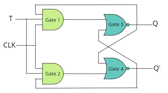
Working Principle of T Flip-Flop
The T flip-flop has two possible cases. We assume the clock signal always HIGH.
| Case | T | CLK | Gate 01 | Gate 02 | Gate 03 / Q | Gate 04 / Q’ |
|---|---|---|---|---|---|---|
| 01 | 0 | 1 | 0 | 0 | Q [No change] | Q’ |
| 02 | 1 | 1 | Q | Q’ | Q’ [toggle] | 0 |
Note: If T is set to HIGH then the T flip flop toggle the previous output i.e. LOW to HIGH or HIGH to LOW.
T Flip-Flop Truth Table
| CLK | T | Q(t+1) |
|---|---|---|
| 1 | 0 | Q [No change] |
| 1 | 1 | Q’ [Toggle] |
T Flip-Flop characteristic table
From the truth table, we only know the present stage of output, but from the characteristic table, we know the present and next stages of output.
| T | Q(t) | Q(t+1) |
|---|---|---|
| 0 | 0 | 0 |
| 0 | 1 | 1 |
| 1 | 0 | 1 |
| 1 | 1 | 0 |
T Flip-Flop K-map
By using K-Map we can get the characteristic equation of T flip-flop.
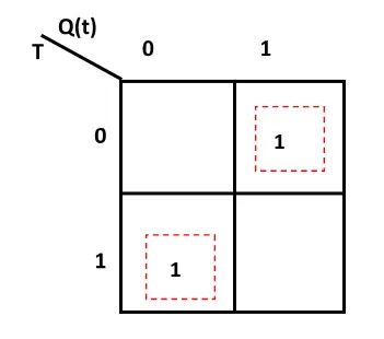
Characteristic Equation of T flip-flop
Q(t+1) = T′Q(t)+TQ(t)′
Or, Q(t+1) = T⊕Q(t)
Application of T Flip-Flop
Frequency Division: One of the primary applications of the T flip-flop is in frequency division circuits. By connecting the output of a T flip-flop to its own input (feedback), you can create a circuit known as a “divide-by-2” counter. This circuit effectively halves the input frequency at the flip-flop’s output. Cascading multiple T flip-flops can create higher division ratios, forming binary counters.
Pulse Generators: T flip-flops can be used as pulse generators. By feeding a repetitive signal into the T input, you can create a square wave output with a frequency that’s a fraction of the input frequency. This is useful in generating timing pulses for various applications.
Oscillators: T flip-flops are utilized in oscillator circuits, specifically in astable multivibrator configurations. When combined with resistors and capacitors, T flip-flops can generate square wave or pulse wave oscillations. These oscillators find applications in clock signal generation, signal testing, and waveform generation.
Digital Counters: T flip-flops can be used in conjunction with other flip-flops to create binary counters. These counters are used for tasks like counting events, measuring time intervals, and controlling sequential processes..
Toggle Circuits: The toggle behavior of the T flip-flop is useful in designing toggle circuits, where the output state changes every time the T input is activated. This can be employed in various control and sequencing applications.