This tutorial will discuss how to design a relay circuit diagram for any DC or AC loads. By using this relay circuit with Arduino, esp32, or any microcontroller you can drive (ON-OFF) any high-power load like a motor, or a heater.
Component List
| Name of Component | Quantity | Purchase Link |
|---|---|---|
| Optocoupler (we are using PC817X) | 1 | Amazon | AliExpress |
| 5V Relay (SRD-05VDC-SL-C) | 1 | Amazon | AliExpress |
| NPN Transistor (TIP122) | 1 | Amazon | AliExpress |
| Schottky diode (1N5819) | 1 | Amazon | AliExpress |
| Any microcontroller (Arduino, Esp32, STM32) | 1 | Amazon | AliExpress |
| Resistor (330R and 1K) | 2 | Amazon | AliExpress |
| 5V Power source | 1 | Amazon | AliExpress |
Affiliate Disclosure: When you click on links to make a purchase, this can result in this website earning a commission. Affiliate programs and affiliations include, but are not limited to Amazon.com
Relay Circuit Diagram

Circuit explanation
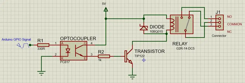
In this relay circuit, we use an optocoupler (PC817x) to separate the high-voltage part of the circuit (relay part) from the low-voltage part. We connect the anode of the optocoupler to the microcontroller (Arduino, esp32, or any microcontroller) signal pin through a 330-ohm resistor, and the cathode connects to the ground. The collector of the optocoupler is connected to a power source (we use a 5-volt power source). The Emmeter of the optocoupler connects to a transistor’s base (we are using TIP122) via a 1 Kilo-ohm resistor.
The transistor collector pin connects to one pin of the relay coil and the ammeter pin of the transistor is connected to the ground. The other side of the relay coil connects to the power source (5V). We also use a Schottky diode across the relay for reverse current protection.
