
In this article you will learn how to build and code a line following robot using conditional logic with Arduino Nano. This article will be divided into several segments which are mentioned in the table of contents.
N.B.: This is a tutorial for a specific type of LFR. You can use other methods to build LFR such as the PID algorithm. Although the circuit diagram of the LFR is given here the instruction to physically build the LFR is absent since one can build in his own style with more efficiency. However, some Tips shall be given throughout the article so that your LFR might be better. Also, in the end of this article there shall be more instructions on how you can do better by improving this code.
While my LFR Contains obstacle avoidance as well. However for simplicity I didn’t add this part in this tutorial.
What is an LFR?
The line follower robot is an automated vehicle that follows a visual line embedded on the surface. This visual line is a path on which the line-follower robot runs. Generally, it uses a black line on a white surface, or you can adjust it as a white line on a black surface.
Where is it used?
Industrial Applications: These robots can be used as automated equipment carriers in industries replacing traditional conveyor belts.
Automobile applications: These robots can also be used as automatic cars running on roads with embedded magnets.
Domestic applications: These can also be used at homes for domestic purposes like floor cleaning etc.
Guidance applications: These can be used in public places like shopping malls, museums etc to provide path guidance.
Circuit Diagram
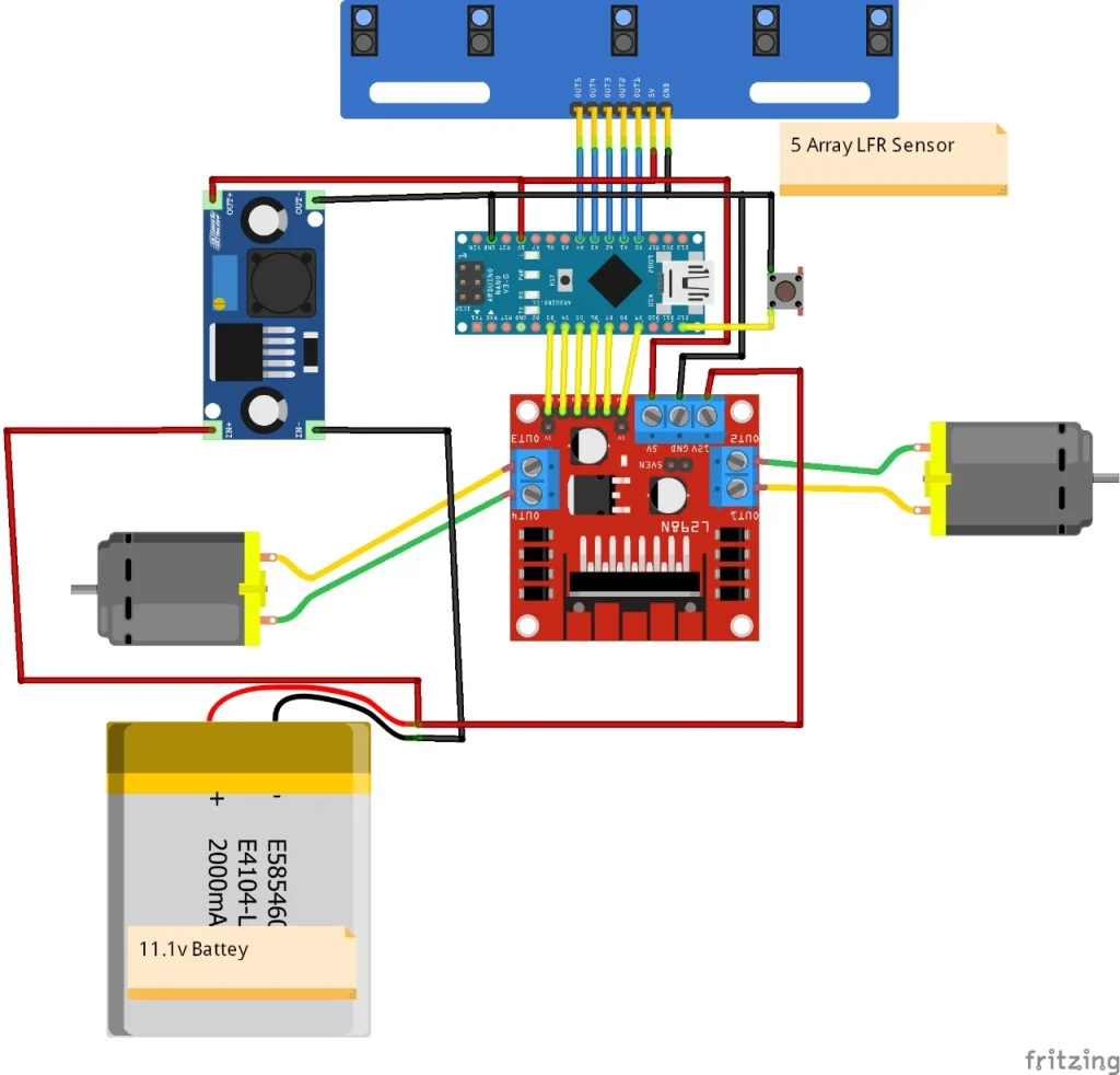
Components List
| Components | Pieces | Purchase Link |
| Arduino Nano | 1 | Amazon | AliExpress |
| 5 Array IR Sensor | 1 | Amazon | AliExpress |
| l298N Motor Driver | 1 | Amazon | AliExpress |
| Buck Converter | 1 | Amazon | AliExpress |
| Mini Breadboard | 1 | Amazon | AliExpress |
| 25 gb 500 rpm DC geared motor | 2 | Amazon | AliExpress |
| Wheels | 2 | Amazon | AliExpress |
| Ball Caster | 1 | Amazon |
| Jumper Wire(M-M, M-F, F-F) | 3 | Amazon |
| Push Button | 1 | Amazon |
| 12v Battery | 1 | Amazon |
| PVC/Plywood | 1 | Amazon |
| Miscellaneous (Screws, Glue, Double Sided Tape) | 1 |
Connection Tables
Arduino with Motor Driver(L298N)
| Motor Driver Pin | Arduino Nano Pin |
| ENA | 9 |
| IN1 | 7 |
| IN2 | 6 |
| IN3 | 5 |
| IN4 | 4 |
| ENB | 3 |
Connection Between Motor Driver, Power Supply and Motor
12V Connector – battery 12V
5V – Buck positive
Gnd – Battery Gnd
L298N OUT1 Port – Motor1 +
L298N OUT2 Port – Motor1 –
L298N OUT3 Port – Motor2 +
L298N OUT4 Port – Motor2 –
5 Array IR Sensor Connection
| Arduino Nano Pin | 5 Array Sensor Pin |
| A0 | OUT1 |
| A1 | OUT2 |
| A2 | OUT3 |
| A3 | OUT4 |
| A4 | OUT5 |
| 5V | 5V |
| GND | GND |
Push Button
Push Button (+) – Arduino Pin D12
Push Button (-) – Arduino GND
LFR Building Tips:
While Building LFR make sure the sensor is closer to the ground. Make sure the line width is greater than the distance between two IR sensors. It is recommended that The LFR body size ratio is 2:3. Also make sure the CG(Center of Gravity) is near the center.
Full Arduino IDE Code
int s1, s2, s3, s4, s5;
int reading;
int lmb = 5, lmf = 4, lms = 3;
int rmb = 6, rmf = 7, rms = 9;
#define spl 9.5
#define spr 9.3
#define stop_timer 150


char flag = 's';
int sum = 0;
int sw = 12;
char cross = 's';
//int light = 2;
uint32_t m1, m2, m3;
void setup() {
  pinMode(rmf, OUTPUT);
  pinMode(rmb, OUTPUT);
  pinMode(rms, OUTPUT);


  pinMode(lmf, OUTPUT);
  pinMode(lmb, OUTPUT);
  pinMode(lms, OUTPUT);
  pinMode(sw, INPUT_PULLUP);
  //pinMode(light, OUTPUT);
  Serial.begin(9600);
}


void loop() {
  int r = button_press();
  if(r == 1){
    line_follow();
  }

}


int pos = 0;
void line_follow(){
 while(1){
 a: sensor();
  //show();
  //code for 90 degree left right or t section

  if(reading == 0b00000){
    if(flag != 's'){

    if(flag == 'r'){
    motor_forward(spl * -13, spr * -13);
      delay(30);
      motor_forward(6.5 * spl, -6.5 * spr);
      while(s1+s2+s3+s4 < 1){
          sensor();
        }
        //motor_forward(-11 * spl, 11 * spr);
       //delay(30);
    flag = 's';
     }
     else if(flag == 'l'){
     motor_forward(spl * -13, spr * -13);
      delay(30);
       motor_forward(-6.5 * spl, 6.5 * spr);
       while(s2+s3+s4+s5 < 1){
           sensor();
       }
       //motor_forward(11 * spl, -11 * spr);
       //delay(30);
     flag = 's';
     }
    }
    else if(pos >= -1 && pos <= 1){
      motor_forward(-14 * spl, -13 * spr);
      delay(100);
      motor_forward(6 * spl, 6 * spr);
      delay(560);
      motor_forward(-9 * spl, -7 * spr);
      delay(50);
      if(sum != 0){ goto a;}
      else{
        motor_forward(6.5 * spl, -6.5 * spr);
      while(s1+s2+s3+s4 < 1){
          sensor();
        }
        motor_forward(12 * spl, -12 * spr);
       delay(60);
      }
    }

    else if(pos > 1){
      motor_forward(6.5 * spl, -6.5 * spr);
       while(sum < 0){
           sensor();
       }
    }
    else if(pos < -1){
      motor_forward(-5.5 * spl, 5.5 * spr);
       while(sum < 0){
           sensor();
       }
    }
  }
  if(sum == 1 || sum == 2){
    if(cross != 's'){
        motor_forward(spl * -9, spr * -9);
        delay(20);
        if(cross == 'r') motor_forward(6.5 * spl, -6.5 * spr);
        while(s2+ s3 + s4 > 0) sensor();
        while(reading != 0b00100 && reading != 0b01000 && reading!= 0b00010) sensor();
        //motor_forward(-8 * spl, 8 * spr);
       //delay(30);
        cross = 's';
      }
    if(reading == 0b00100){
      //code if the robot came from left or right to straight
      //making it balance by applying some force on the opposite direction
      if(pos <= 3 && pos >= -3 & pos != 0){
          (pos > 0)? motor_forward(-9.5 * spl, 9.5 * spr): motor_forward(9.5 * spl, -9.5 * spr);
          if(pos == 1 || pos == -1){
            (pos>0)? delay(pos * 14): delay(-pos * 14);
            //motor_forward(9.5 * spl, 9.5 * spr);
            //delay(15);
           }
           /*else if(pos == 2 || pos == -2){
            (pos>0)? delay(pos * 11): delay(-pos * 11);
           }*/
           else if(pos == 3 || pos == -3){
            (pos>0)? delay(pos * 11): delay(-pos * 11);
           }
          pos = 0;
        }
      motor_forward(spl * 9.5, spr * 9.5);
    }
    //right side portion
    else if(reading == 0b00110) motor_forward(spl * 8.5, spr * 3);
    else if(reading == 0b00010){
      motor_forward(spl * 9.5, spr * 0);
      if(pos < 1) pos = 1;
    }
    else if(reading == 0b00011){
      motor_forward(spl * 8.5, spr * -3);
      if(pos < 2) pos = 2;
    }
    else if(reading == 0b00001){
      motor_forward(spl * 9.5, spr * -4.5);
      if(pos < 3) pos = 3;
    }
    //left side portion
    else if(reading == 0b01100) motor_forward(spl * 3, spr * 8.5);
    else if(reading == 0b01000){
      motor_forward(spl * 0, spr * 9.5);
      if(pos > -1) pos = -1;
    }
    else if(reading == 0b11000){
      motor_forward(spl * -3, spr * 8.5);
      if(pos > -2) pos = -2;
    }
    else if(reading == 0b10000){
      motor_forward(spl * -4.5, spr * 9.5);
      if(pos > -3) pos = -3;
    }
  }
  if((sum == 2 || sum == 3 || sum == 4) && flag != 't'){
    if(s1 == 0 && s5 == 1 && (s2 + s3 + s4) > 0){
        flag = 'r';
        if(sum == 3 || sum == 4){
        while(s5 == 0 && s1 == 1) sensor();
        if(sum != 0) cross = 'r';
         }
      }
    else if(s1 == 1 && s5 == 0 && (s2 + s3 + s4) > 0) flag = 'l';
    if((s1 == 0 && s5 == 1 && (s2 + s3 + s4) > 0) || (s1 == 1 && s5 == 0 && (s2 + s3 + s4) > 0)){m1 = millis();}
  }
  m2 = millis();
  if(m2 - m1 > 100) flag = 's';
  if(sum == 5){
    flag = 'r';
    m3 = millis();
    while(s1 == 1 || s5 == 1){
      sensor();
      if(millis() - m3 > stop_timer){
        motor_forward(0, 0);
        while(sum == 5) sensor();
        goto a;
      }
    }
    delay(5);
    sensor();
    if(sum != 0) cross = 'r';
  }
}
}
void motor_forward(int a, int b){
  if(a>=0){
    digitalWrite(lmf, 1);
    digitalWrite(lmb, 0);
  }
  else{
    a=-a;
    digitalWrite(lmf, 0);
    digitalWrite(lmb, 1);
  }
  if(b>=0){
    digitalWrite(rmf, 1);
    digitalWrite(rmb, 0);
  }
  else{
    b=-b;
    digitalWrite(rmf, 0);
    digitalWrite(rmb, 1);
  }
  analogWrite(lms,a);
  analogWrite(rms,b);
}


int button_press(){
    int count = 0;
 p:   int t = 0;
    if(digitalRead(sw) == 0){
        while(digitalRead(sw) == 0){
            delay(1); t++;
          }
        if(t > 15){
              count++;
              t = 0;
              while(digitalRead(sw) == 1){
                    delay(1);
                    t++;
                    if(t > 1000) return count;
                }
              goto p;
          }
      }
   return count;


 }
void sensor(){
  sum = 0;
  s1 = analogRead(0);
  s2 = analogRead(1);
  s3 = analogRead(2);
  s4 = analogRead(3);
  s5 = analogRead(4);


  if(s1 < 400) s1 = 1;
  else s1 = 0;
  if(s2 < 400) s2 = 1;
  else s2 = 0;
  if(s3 < 400) s3 = 1;
  else s3 = 0;
  if(s4 < 400) s4 = 1;
  else s4 = 0;
  if(s5 < 400) s5 = 1;
  else s5 = 0;


  reading = s1 * 16 + s2 * 8 + s3 * 4 + s4 * 2 + s5 * 1;
  sum = s1 + s2 + s3 + s4 + s5;
 }
Code Explanation
Variable Declarations
- 5 Array Sensor: s1, s2, s3, s4, s5 represent the sensor readings.
- Motor pins: lmb, lmf, lms for left motor; rmb, rmf, rms for right motor.
- Thresholds: spl and spr define speed multipliers for motors.
- State tracking: Flags like flag, cross, and pos monitor robot state and path position.
Sensor Variables
int s1, s2, s3, s4, s5;
- These represent the readings from the line sensors.
- Each sensor detects if it is over the line or not:
- 1 means the sensor is over the line.
- 0 means the sensor is not over the line.
int reading;
- Combines the sensor readings (s1, s2, …, s5) into a single binary value.
- Example: If s1=1, s2=0, s3=1, s4=0, s5=0, then reading = 0b10100.
- This makes it easier to analyze the robot’s position relative to the line.
These variables are used in sensor() function. Which goes like this,
void sensor(){
  sum = 0;
  s1 = analogRead(0);
  s2 = analogRead(1);
  s3 = analogRead(2);
  s4 = analogRead(3);
  s5 = analogRead(4);


  if(s1 < 400) s1 = 1;
  else s1 = 0;
  if(s2 < 400) s2 = 1;
  else s2 = 0;
  if(s3 < 400) s3 = 1;
  else s3 = 0;
  if(s4 < 400) s4 = 1;
  else s4 = 0;
  if(s5 < 400) s5 = 1;
  else s5 = 0;


  reading = s1 * 16 + s2 * 8 + s3 * 4 + s4 * 2 + s5 * 1;
  sum = s1 + s2 + s3 + s4 + s5;
Initialize Variables
sum = 0;
Resets the sum variable, which tracks the number of sensors detecting the line.
Read Analog Values
s1 = analogRead(0);
s2 = analogRead(1);
s3 = analogRead(2);
s4 = analogRead(3);
s5 = analogRead(4);
- Reads the raw analog values from the 5 sensors.
- These values typically range from 0 to 1023, where:
- Low values (closer to 0) indicate the presence of the line (black surface).
- High values (closer to 1023) indicate the absence of the line (white surface).
Convert Analog to Binary
if (s1 < 400) s1 = 1; else s1 = 0;
if (s2 < 400) s2 = 1; else s2 = 0;
if (s3 < 400) s3 = 1; else s3 = 0;
if (s4 < 400) s4 = 1; else s4 = 0;
if (s5 < 400) s5 = 1; else s5 = 0;
- Each sensor’s analog value is thresholded:
- If the value is less than 400, the sensor detects the line and is set to 1.
- Otherwise, it is set to 0.
- The threshold value (400) may vary depending on the sensor and environmental conditions.
Tips: Take your sensor near to the line. Record the lowest value for black and the highest value for white line. Take the avg. of those as the threshold.
Compute Binary Representation
reading = s1 * 16 + s2 * 8 + s3 * 4 + s4 * 2 + s5 * 1;
- Combines the binary states (s1 to s5) into a single binary number (reading):
- s1 represents the leftmost sensor (multiplied by 16).
s5 represents the rightmost sensor (multiplied by 1).
Example: If s1=1, s2=0, s3=1, s4=0, s5=1, then:
reading = 1 * 16 + 0 * 8 + 1 * 4 + 0 * 2 + 1 * 1 = 21 (binary 10101)
Count Active Sensors
sum = s1 + s2 + s3 + s4 + s5;
- Adds up the values of s1, s2, s3, s4, and s5 to compute the total number of sensors detecting the line.
- Example:
- If s1=1, s2=0, s3=1, s4=0, s5=1, then sum = 1 + 0 + 1 + 0 + 1 = 3.
Motor Pins
The motor_forward() function is responsible for controlling the motors to move the robot in a specific direction based on speed inputs for the left and right motors. It is a crucial part of the line-following robot’s ability to navigate.
void motor_forward(int a, int b){
  if(a>=0){
    digitalWrite(lmf, 1);
    digitalWrite(lmb, 0);
  }
  else{
    a=-a;
    digitalWrite(lmf, 0);
    digitalWrite(lmb, 1);
  }
  if(b>=0){
    digitalWrite(rmf, 1);
    digitalWrite(rmb, 0);
  }
  else{
    b=-b;
    digitalWrite(rmf, 0);
    digitalWrite(rmb, 1);
  }
  analogWrite(lms,a);
  analogWrite(rms,b);
}
void motor_forward(int a, int b)
Parameters:
- a: Speed for the left motor. Positive for forward, negative for backward.
- b: Speed for the right motor. Positive for forward, negative for backward.
Function Logic
Control the Left Motor
if (a >= 0) {
    digitalWrite(lmf, 1);
    digitalWrite(lmb, 0);
} else {
    a = -a;
    digitalWrite(lmf, 0);
    digitalWrite(lmb, 1);
}
- The left motor’s speed (a) is checked:
- Positive (a >= 0): The left motor moves forward.
- lmf (left motor forward) is set to HIGH (1).
- lmb (left motor backward) is set to LOW (0).
- Negative (a < 0): The left motor moves backward.
- a is converted to a positive value using a = -a.
- lmf is set to LOW (0).
- lmb is set to HIGH (1).
- Positive (a >= 0): The left motor moves forward.
Control the Right Motor
if (b >= 0) {
    digitalWrite(rmf, 1);
    digitalWrite(rmb, 0);
} else {
    b = -b;
    digitalWrite(rmf, 0);
    digitalWrite(rmb, 1);
}
- The right motor’s speed (b) is checked:
- Positive (b >= 0): The right motor moves forward.
- rmf (right motor forward) is set to HIGH (1).
- rmb (right motor backward) is set to LOW (0).
- Negative (b < 0): The right motor moves backward.
- b is converted to a positive value using b = -b.
- rmf is set to LOW (0).
- rmb is set to HIGH (1).
- Positive (b >= 0): The right motor moves forward.
Set Motor Speed
analogWrite(lms, a);
analogWrite(rms, b);
- Sends a PWM (Pulse Width Modulation) signal to control the speed of the motors:
- lms (left motor speed) is set to the absolute value of a.
- rms (right motor speed) is set to the absolute value of b.
- The values for a and b should be between 0 and 255, where:
- 0 represents no motion (stopped).
- 255 represents full speed.
Tips: The motors might not move the desired direction at first try. If it happens just shuffle the lmb, lmf, rmb, rmf pin number and eventually you shall get your desired rotating direction and the right pin.
Thresholds
spl and spr define speed multipliers for motors.
Tips: To ensure your motor moves in a straight line, use the following command: motor_forward(10 * spl, 10 * spr);.For the values of spl and spr, set them to values that make the LFR (Left Front Right) go absolutely straight. For example, in my case, the values are 9.5 for spl and 9.3 for spr. These values may vary depending on the motor since every motor has its own discrepancies.
button_press Function
The button_press() function handles the interaction with a button to control the robot’s operational state. It detects button presses, counts the number of presses, and determines if the button was held for an extended time.
int button_press(){
    int count = 0;
 p:   int t = 0;
    if(digitalRead(sw) == 0){
        while(digitalRead(sw) == 0){
            delay(1); t++;
          }
        if(t > 15){
              count++;
              t = 0;
              while(digitalRead(sw) == 1){
                    delay(1);
                    t++;
                    if(t > 1000) return count;
                }
              goto p;
          }
      }
   return count;

  }
int button_press()
Returns:
- count: The number of button presses detected.
- Each short press increments the count.
- A long press (holding the button) ends the count and returns it.
Variable Initialization
int count = 0;
int t = 0;
- count: Tracks the total number of button presses.
- t: Measures the duration (in milliseconds) the button is held down.
Outer Loop to Detect Button Press
p: if (digitalRead(sw) == 0) {
- digitalRead(sw) checks the state of the button (sw pin):
- 0: Button is pressed.
- 1: Button is released.
- The loop starts when the button is detected as pressed.
Inner Loop to Measure Button Hold Time
while (digitalRead(sw) == 0) {
    delay(1);
    t++;
}
- While the button is being held down:
- A delay of 1 millisecond is introduced.
t is incremented to count how long the button is held.
Check the Duration of the Press
if (t > 15) {
    count++;
    t = 0;
- If the button was held for more than 15 milliseconds, it is considered a valid press:
- The press is counted by incrementing count.
- t is reset to 0 for the next detection.
Wait for Button Release
while (digitalRead(sw) == 1) {
    delay(1);
    t++;
    if (t > 1000) return count;
}
- Once the button is released:
- Another loop waits for the button to be pressed again.
- If the button is held for more than 1000 milliseconds during this period:
The function exits and returns the current count.
Repeat Detection
goto p;
The function loops back to p to detect additional presses or holds.
Main part of the Code
The line_follow() function is the core logic that keeps the robot on the line and manages its movement based on sensor readings. Here’s a detailed breakdown of its operation:
Overview
The line_follow() function is structured as an infinite loop (while(1)) where the robot constantly reads sensor data and adjusts motor movements to follow the line. It handles various scenarios, including straight paths, turns, and intersections.
Key Sections of line_follow()
Initial Sensor Reading
a: sensor();
- The sensor() function reads the line sensors and updates:
- reading: Binary representation of the line position.
- sum: Total number of sensors detecting the line.
- Label a is used for looping back in certain conditions.
2.2 Detecting a Lost Line
if (reading == 0b00000) {
- If no sensors detect the line, the robot assumes the line is lost.
- Based on the previous state (flag), it attempts to recover:
- flag == ‘r’ (Right Turn Recovery):
- Moves backward briefly to reposition.
- Rotates left until it detects the line again.
- flag == ‘l’ (Left Turn Recovery):
- Moves backward briefly to reposition.
- Rotates right until it detects the line again.
- flag == ‘s’ (Straight Path Recovery):
- Moves backward and forward to realign itself with the line.
- flag == ‘r’ (Right Turn Recovery):
Tips: Flag states will be explained later
Handling a Single-Line Path
if (sum == 1 || sum == 2) {
- The robot follows a single line by adjusting motor speeds:
- reading == 0b00100: Centered on the line; moves forward.
- Right Side (e.g., reading == 0b00010, reading == 0b00001):
- Adjusts speed to turn slightly right.
- Updates pos to track the robot’s position.
- Left Side (e.g., reading == 0b01000, reading == 0b10000):
- Adjusts speed to turn slightly left.
- Updates pos to track the robot’s position.
Handling Intersections or T-sections
if ((sum == 2 || sum == 3 || sum == 4) && flag != 't') {
- Detecting Turns:
- If sensors detect a line on the extreme left (s1) or right (s5), the robot flags a left or right turn.
- Example: If s1 == 1 (left edge detected), flag = ‘l’.
- Handling Cross Sections:
- If all sensors detect the line (sum == 5), the robot recognizes a cross-section and temporarily stops.
- After stopping, it decides whether to turn or move straight, based on additional logic.
Realigning on Straight Paths
if (reading == 0b00100) {
- Even on a straight path, slight deviations are corrected:
- If pos indicates a deviation:
- Applies a corrective force in the opposite direction.
- Brings the robot back to the center of the line (pos = 0).
- If pos indicates a deviation:
Continuous Adjustments
if (pos > 1) {
    motor_forward(6.5 * spl, -6.5 * spr);
    while (sum < 0) {
        sensor();
    }
}
- If the robot deviates significantly:
- Right Deviation (pos > 1): Rotates left.
- Left Deviation (pos < -1): Rotates right.
- Ensures the robot realigns before continuing.
Handling Stops or Special Conditions
if (millis() - m3 > stop_timer) {
    motor_forward(0, 0);
    while (sum == 5) {
        sensor();
    }
    goto a;
}
- If the robot detects a full stop (e.g., at an intersection) for a prolonged period (stop_timer), it halts.
- Waits until the path is clear or conditions change, then resumes operation.
Motor Control
The function frequently calls motor_forward(a, b):
- Controls motor speeds based on sensor readings.
- Adjusts direction (forward/backward) to align with the line.
Tips: The values here are adjusted based on my LFR weight and configuration. It will vary from case to case. So do the adjustments one by one. It is also recommended to build the code line by line by thorough testing not at once.
Break
The line_follow function contains logic to stop the robot by reversing the motors briefly, which acts as a braking mechanism. This is useful when the robot encounters certain conditions, such as losing track of the line (e.g., when all sensors are inactive).
Relevant Code Snippet
Here is the portion of the function responsible for braking using motor reversal:
Reverse Motors to Stop the Robot
motor_forward(spl * -13, spr * -13);
delay(30);
- motor_forward() is called with negative speed values, which reverses the motors.
- delay(30) creates a short burst of motor reversal to stop the robot’s forward momentum.