
Logic gates serve as the fundamental components of all digital systems. These electronic circuits have one or more inputs and a single output, with the output determined by a specific logical relationship between the inputs. Examples of such gates include the AND, OR, NOT, NAND, and NOR gates, each named according to the logic they implement.
What is a Logic Gate?
A logic gate is an electronic circuit that performs logical operations inside a digital device. A logic gate is made by the combination of a resistor, diode, and transistor. A Logic gate receives one or multiple inputs and gives only one output. It takes input and performs logical operations. Boolean algebra is the base for logical operation in digital devices. Boolean algebra consists of two states – true or false. In a binary system true is represented as 1 and false is represented as 0.
Types of Logic Gates
Logic gates are classified into four major types. They are given below:
- Basic logic gate
- Universal gate
- Exclusive gate
- Compound or complex gate
In this blog, we will learn about the first three types of logic gates.
Basic logic gates
There are three types of basic logic gates used in digital devices:
- AND GATE
- OR GATE
- NOT GATE
AND GATE
Definition
An AND gate can take two or more inputs and deliver one output. It only gives output logic 1 when all the inputs are logic 1. If an input is logic 0 the output will be logic 0.
Boolean expression of 2-input AND gate is:
Y = A.B
Boolean expression of n number of input AND gate is:
Y = A.B.C.D…
Where A, B, C, D are the inputs and Y is the output.
Truth Table
The truth table of two inputs AND gate is given below:
| A(1st input) | B(2nd input) | Y(output) |
|---|---|---|
| 0 | 0 | 0 |
| 0 | 1 | 0 |
| 1 | 0 | 0 |
| 1 | 1 | 1 |
Symbol
The symbol of the AND gate is:

Example
IC 7408 is an example of an AND gate. It has four 2-input AND gates inside it.
OR GATE
Definition
OR gate can take two or more inputs and only give one output. It only returns output logic 0 if all the inputs are logic 0. If only one input is logic 1 the output will be logic 1.
Boolean expression of 2-input OR gate is:
Y = A + B
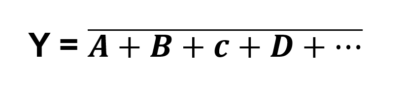
Boolean expression of n number of input OR gate is:
Y = A + B + C + D +…
Where A, B, C, D are the inputs and Y is the output.
Truth Table
The truth table of two inputs OR gate is given below:
| A(1st input) | B(2nd input) | Y(output) |
|---|---|---|
| 0 | 0 | 0 |
| 0 | 1 | 1 |
| 1 | 0 | 1 |
| 1 | 1 | 1 |
Symbol

Example
IC 7432 is an example of OR gate which has four 2-input OR gates.
NOT GATE
Definition
NOT gate can take only one input and give one output. It converts logic 1 to logic 0 and logic 0 to logic 1. That’s why it is also called an inverter.
Boolean expression of NOT gate is:
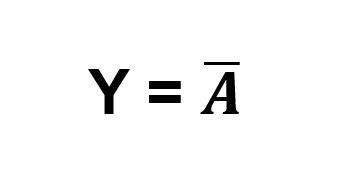
Where A is the input and Y is the output. The bar(‘ over the input A means NOT operation for input A.
Truth Table
The truth table of NOT gate is given below:
| A(1st input) | Y(output) |
|---|---|
| 0 | 1 |
| 1 | 0 |
Symbol
The symbol of the NOT gate is:

Example
For example, we can consider IC 7404 which has 6 NOT gates.
Universal Gates
There are two types of universal gates. They are:
- NAND GATE
- NOR GATE
All kinds of logic circuits can be implemented using only one type of universal gate. For that reason, they are called universal gates.
NAND GATE
Definition
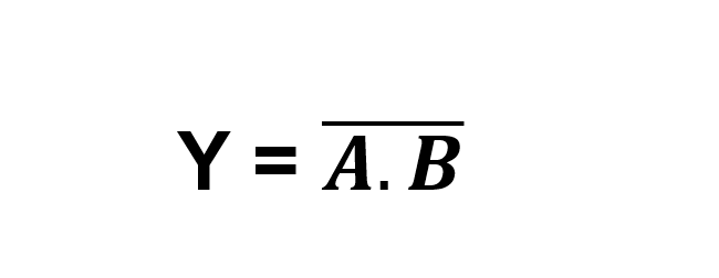
NAND gate is the combination of an AND gate followed by a NOT gate. It performs the opposite operation of the AND gate. It can take two or more inputs and only one output. Boolean expression of 2-input NAND gate is:
Boolean expression of n number of input NAND gate is:
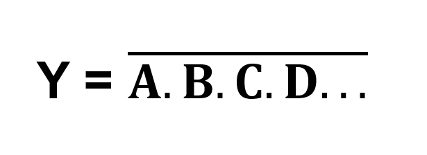
Where A, B, C, D are inputs and Y is the output.
Truth Table
The truth table of the 2-input NAND gate is given below:
| A(1st input) | B(2nd input) | Y(output) |
|---|---|---|
| 0 | 0 | 1 |
| 0 | 1 | 1 |
| 1 | 0 | 1 |
| 1 | 1 | 0 |
Symbol
The symbol of the NAND gate is:

Example
IC 7400 is an example of NAND gate that contains four 2-input NAND gates.
NOR GATE
Definition
NOR gate does the opposite operation of the OR gate. NOR gate can be implemented by one OR gate followed by a NOT gate. It can take two or more inputs and give only one output. It gives output logic 1 if all the inputs are logic 0. If an input is logic 1 then the output will be logic 0.
Boolean expression of 2-input NOR gate given below:
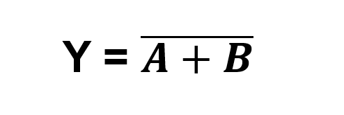
Boolean expression of n number of input NOR gate is given below:
Where A, B, C, D are inputs and Y is the output.
Truth Table
The truth table of the 2-input NOR gate is given below:
| A(1st input) | B(2nd input) | Y(output) |
|---|---|---|
| 0 | 0 | 1 |
| 0 | 1 | 0 |
| 1 | 0 | 0 |
| 1 | 1 | 0 |
Symbol
The symbol NOR gate is given below:

Example
IC 7402 is an example of NOR gate. This IC has four 2-input NOR gates.
Exclusive Gates
There are two exclusive gates available. They are:
- XOR GATE
- X-NOR GATE
XOR GATE
Definition
XOR gate can only take two inputs and produce one output. 2-input XOR gate gives output logic 1 if two inputs are in different logic states. It also produces output logic 1 if there are an odd number of inputs in logic 1.
Boolean expression of the XOR gate is given below:
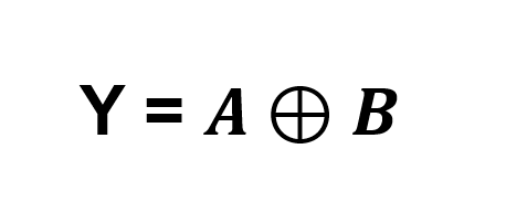
Where A and B are the input and Y is the output.
Truth Table
The truth table of the XOR gate is given below:
| A(1st input) | B(2nd input) | Y(output) |
|---|---|---|
| 0 | 0 | 0 |
| 0 | 1 | 1 |
| 1 | 0 | 1 |
| 1 | 1 | 0 |
Symbol

Example
IC 7486 is an example of the implementation of XOR gate. It has four 2-input XOR gates.
X-NOR GATE
Definition
X-NOR gate does the opposite operation of the XOR gate. It can be implemented using one XOR gate followed by a NOT gate. It produces output logic 1 if two inputs are in the same logic state.
Boolean expression of the X-NOR gate is given below:
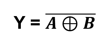
Where A and B are the inputs and Y is the output.
Truth Table
| A(1st input) | B(2nd input) | Y(output) |
|---|---|---|
| 0 | 0 | 1 |
| 0 | 1 | 0 |
| 1 | 0 | 0 |
| 1 | 1 | 1 |
Symbol
The symbol of the X-NOR gate is given below:

Example
IC 74266 is an example of X-NOR gate. It has four 2-input X-NOR gates.
Recap
A recap of all types of logic gates is given below:
- Logic Gate: Eelectronic circuits in a digital system that perform logical operations on input and give an output.
- Types of Logic Gates:
- Basic Gates: AND gate, OR gate, NOT gate.
- AND: Output is 1 only if all inputs are 1.
- OR: Output is 1 if any input is 1.
- NOT: Output is the opposite of input.
- Universal Gates: NAND gate and NOR gate. Each universal gate Can implement all types of logic circuits.
- NAND: Opposite of AND gate.
- NOR: Opposite of OR gate.
- Exclusive Gates: XOR gate and XNOR gate.
- XOR: Output is 1 if inputs are different (for 2-input).
- XNOR: Output is 1 if inputs are the same (for 2-input).
- Basic Gates: AND gate, OR gate, NOT gate.