
Welcome to our comprehensive guide on controlling a servo motor using the STM32 microcontroller. In this tutorial, we’ll delve into the fundamental workings of servo motors and demonstrate how to manipulate them using PWM signals generated by an STM32 microcontroller. To help you grasp these concepts, we’ll build an example project on the STM32 Nucleo Development Board using the STM32CubeIDE.
We have previously published a tutorial on generating PWM signals with the STM32 Microcontroller. Please ensure you read that tutorial before beginning this one.
Understanding Servo Motors
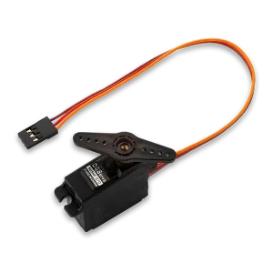
The functionality of servo motors relies on a feedback system that ensures accurate positioning. At the heart of a servo motor are a small DC motor, a control circuit, a potentiometer (used for positional feedback), and a gear system for torque enhancement.
The control circuit receives a PWM signal that dictates the desired position. It then uses the potentiometer’s feedback to adjust the motor’s position until it matches the command, ensuring precise movement control.
Servo motors fall into two main categories: rotary and linear. Rotary servo motors, which are capable of turning in a range of 0 to 180 degrees, 360 degrees, or even continuous rotation, depending on the model, are commonly found in robotic joints, camera tracking systems, and RC vehicles.
On the other hand, linear servo motors convert rotary motion into linear motion and are used in devices like 3D printers and CNC machines.
In this tutorial, we will interface 180-degree rotary servo motors with STM32 Microcontroller.
How to control a Servo Motor
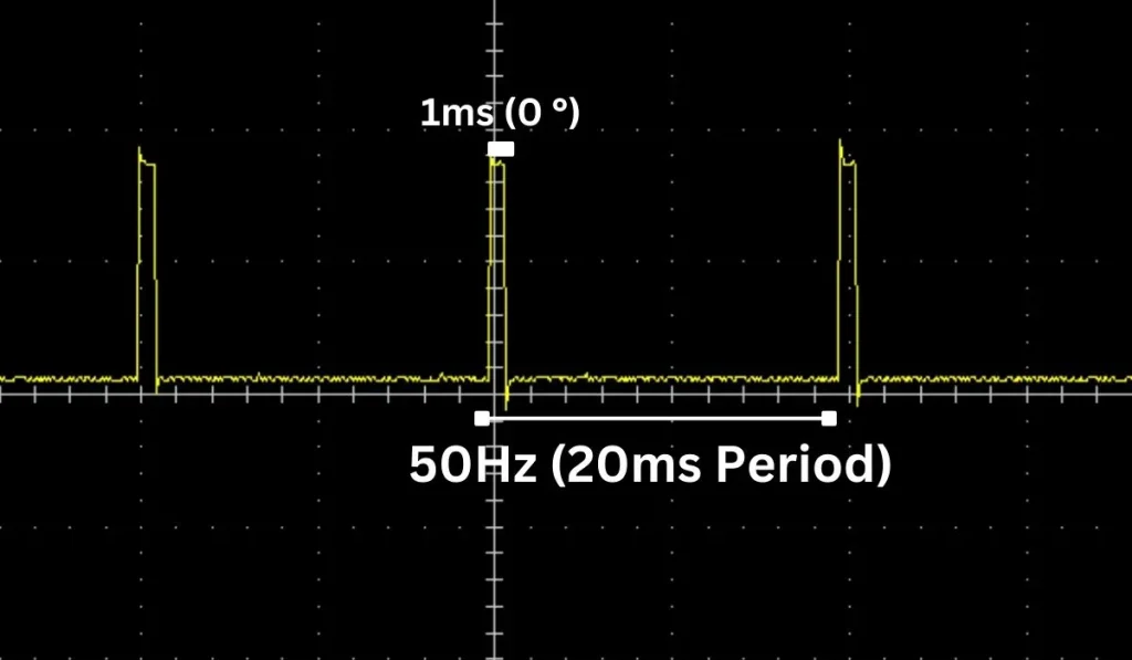
To precisely control a servo motor, the technique of Pulse Width Modulation (PWM) is employed, where the position of the servo’s arm is determined by the length of time the signal remains high.
For the servo to reach a position at the start of its range, the PWM signal stays high for 1 millisecond, indicating a 0-degree orientation.
For a midpoint orientation at 90 degrees, the duration of the high signal is extended to 1.5 milliseconds.
To achieve the maximum range of motion at 180 degrees, the signal’s high phase lasts for 2 milliseconds.
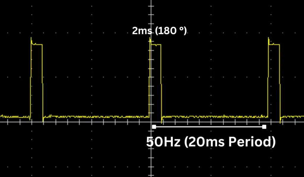
These control signals are sent with a repetition rate that maintains a 20-millisecond gap between pulses, equivalent to a control frequency of 50 Hz, ensuring the servo motor operates smoothly and maintains its positions with precision.
Please Note: Sometimes we found that some of the servo Motors were not rotating the full 180 degrees at 2 milliseconds as they should. So, you may need to test the servo using oscilloscopes or logic analyzer at which duty cycle servo rotates full 0 to 180 degrees. In some cases from 0.5 ms to 2.5 ms, it worked well.
Controlling Servo Motor using STM32 Microcontroller: The Project
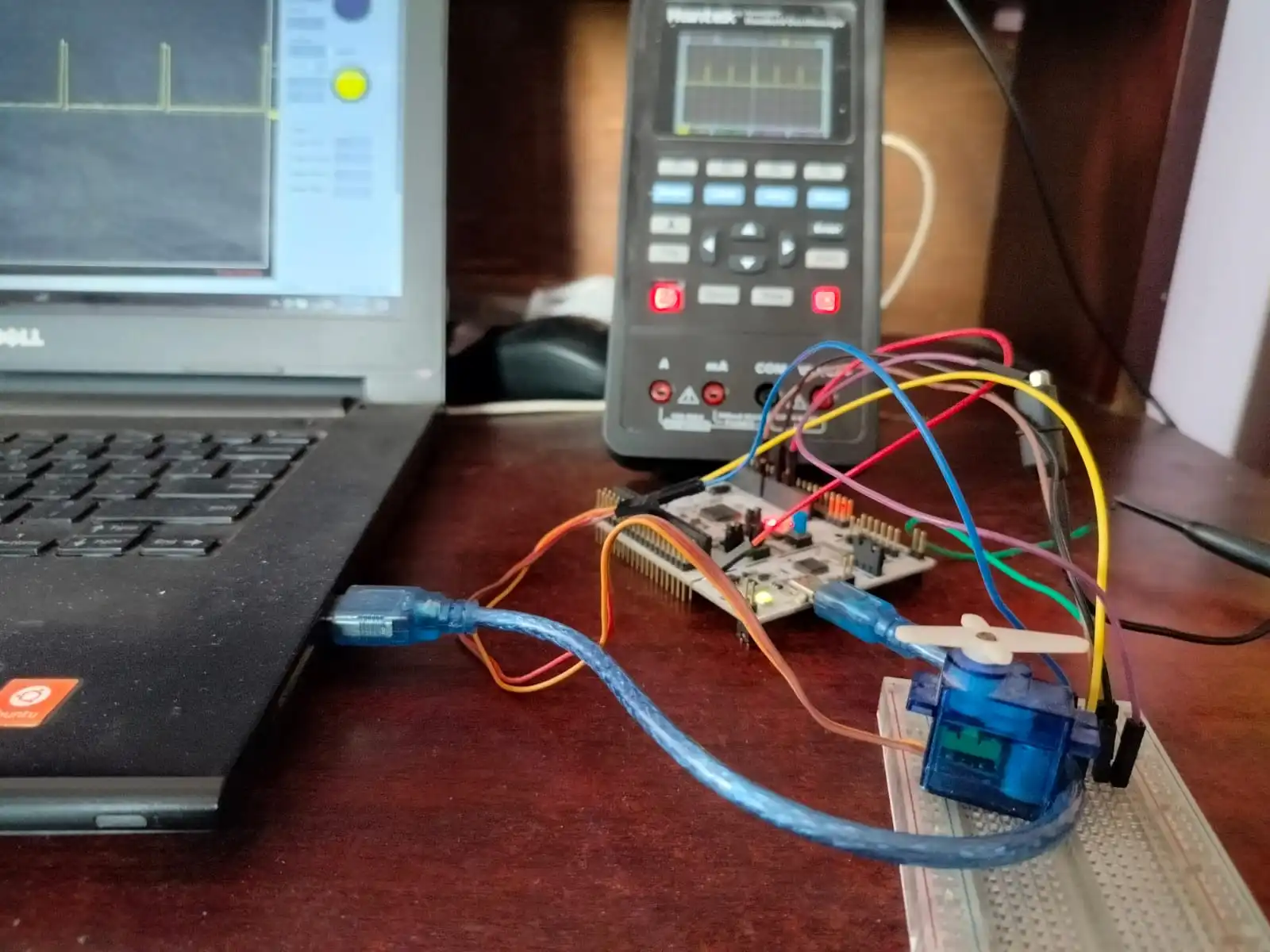
In this section of the tutorial, we will build a small project by using the STM32F446RE NUCLEO Board and a Servo Motor in STM32CubeIDE. We will use a small 180-degree servo motor and rotate it 0 to 180 degrees clockwise and 180 to 0 degrees counter clockwise continuously.
Component List
| Component Name | Quantity | Purchase Link |
|---|---|---|
| STM32 Development Board | 1 | Amazon | Amazon |
| Servo Motor | 1 | Amazon |
| Breadboard | 1 | Amazon |
| Jumper Wire Set | 1 | Amazon |
| 5V Power Supply | 1 | Amazon |
For troubleshooting, some extremely useful test equipment
| Equipment Name | Purchase Link |
|---|---|
| Best Oscilloscope for Professionals | Amazon |
| Best Oscilloscope for Beginners and Hobbyists | Amazon |
| Logic Analyzer | Amazon |
| Best Budget Multimeter | Amazon |
| Adjustable Bench Power Supply | Amazon |
Circuit Diagram
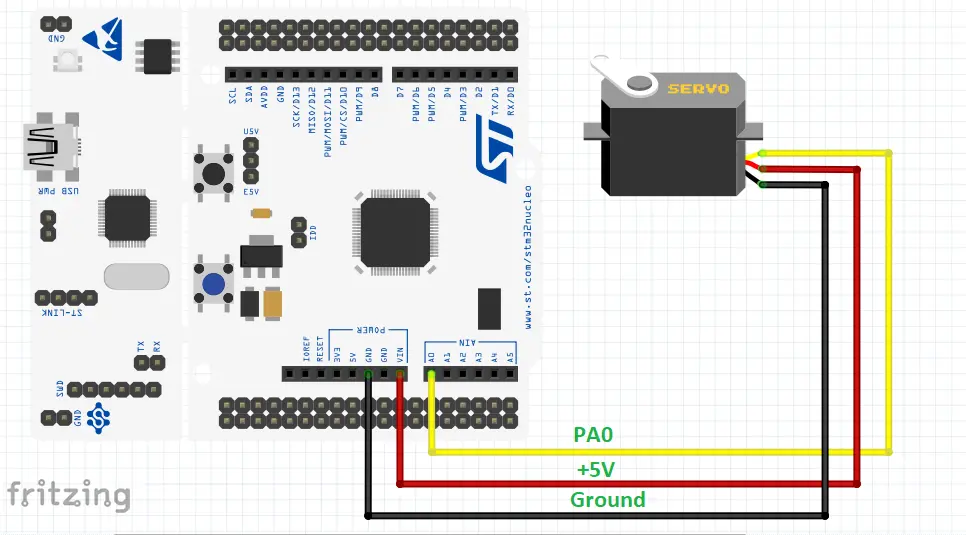
Please Note: Power the servo motor using an external power supply. In this circuit, we use STM32F446RE NUCLEO Board internal power supply which is not a good practice for a professional project.
Pin Connections
| STM32 NUCLEO Board | Servo Motor |
|---|---|
| +5V (please use external power supply) | Red Wire |
| Ground | Brown Wire |
| Port A Pin 0 (PA0) | Yellow Wire |
Preparing STM32CubeIDE
To create a project in Stm32CubeIDE, please visit our previous tutorial. The link is given below:
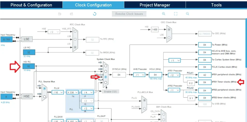
After creating the STM32CubeIDE project, from the CubeMX perspective open the Clock Configuration setting and select the clock source (HSI or HSE). We selected the Internal clock source (HSI) of 16 MHz and generated an 84MHz clock using the PLL of the STM32 microcontroller for this example project.
We use the Timer 2 peripheral of STM32F445RE MCU which is a part of the APB1 Timer Clock. We also configure the APB1 Timer Clock as 84 MHz. The Clock Configuration image is given below.
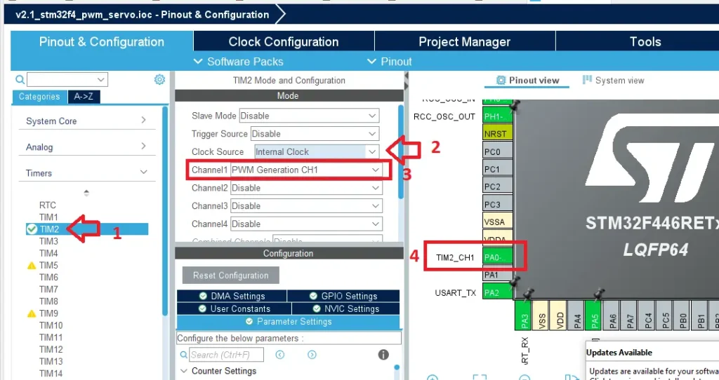
After that click on Pinout & Configuration tab and select your Timer. We use Timer 2 (TIM2) for this servo project. Then go to the Mode section of Timer 2 and select Clock Source as Internal Clock and Channel as PWM generation CH1.
Also, select the Port and Pin where you want to generate the PWM signal. In our case, we use Port A Pin 0 (PA0) for Timer 2 PWM generation Channel 1.
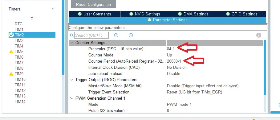
After that click on Parameters Settings and change the Prescaler and Period value according to your requirements. We set the prescaler as 84 to configure the Timer clock of 1MHz.
So, Timer Clock Speed = 84MHz/84 = 1MHz
Also, we set the Counter Period (AutoReload Register) to 20000. It means when the Counter Period reaches 20000 the PWM duty cycle will be 100% with a period of 20 milliseconds or 50 Hz. frequency.
So, Frequency = 1000000 Hz/20000 = 50Hz
Please Note: For both the parameters, we add -1 because the Prescalar Register and the AutoReload Register of STM32 already add 1 in their register setup.
Code Explanation
void setServoAngle(uint32_t angle) {
   if (angle > 180) angle = 180;
   uint32_t minPulseWidth = 1000; // 1ms pulse width at a 1MHz clock
   uint32_t maxPulseWidth = 2000; // 2ms pulse width
   uint32_t pulse = ((angle * (maxPulseWidth - minPulseWidth)) / 180) + minPulseWidth;
   __HAL_TIM_SET_COMPARE(&htim2, TIM_CHANNEL_1, pulse); // Changed to TIM2, Channel 1
}
The setServoAngle(uint32_t angle) function is designed to control the position of a servo motor by generating a corresponding PWM signal based on the specified angle as a parameter.
It first ensures the angle does not exceed 180 degrees, then calculates the appropriate PWM pulse width by linearly interpolating between the predefined minimum (1 millisecond) and maximum (2 milliseconds) pulse widths based on a 0 to 180-degree range.
linear interpolation formula:
uint32_t pulse = ((angle * (maxPulseWidth - minPulseWidth)) / 180) + minPulseWidth;
This pulse width calculation is used to set the PWM duty cycle via the __HAL_TIM_SET_COMPARE() function, which adjusts the output on a timer channel (TIM2, Channel 1) to control the servo’s mechanical position accurately.
Full Code
/* USER CODE BEGIN Header */
/**
  ******************************************************************************
  * @file           : main.c
  * @brief          : Main program body
  ******************************************************************************
  * @attention
  *
  * Copyright (c) 2024 STMicroelectronics.
  * All rights reserved.
  *
  * This software is licensed under terms that can be found in the LICENSE file
  * in the root directory of this software component.
  * If no LICENSE file comes with this software, it is provided AS-IS.
  *
  ******************************************************************************
  */
/* USER CODE END Header */
/* Includes ------------------------------------------------------------------*/
#include "main.h"

/* Private variables ---------------------------------------------------------*/
TIM_HandleTypeDef htim2;

UART_HandleTypeDef huart2;

/* Private function prototypes -----------------------------------------------*/
void SystemClock_Config(void);
static void MX_GPIO_Init(void);
static void MX_USART2_UART_Init(void);
static void MX_TIM2_Init(void);
/* USER CODE BEGIN PFP */

/* USER CODE END PFP */

/* Private user code ---------------------------------------------------------*/
/* USER CODE BEGIN 0 */
void setServoAngle(uint32_t angle) {
    if (angle > 180) angle = 180;
    uint32_t minPulseWidth = 1000; // 1ms pulse width at a 1MHz clock
    uint32_t maxPulseWidth = 2000; // 2ms pulse width
    uint32_t pulse = ((angle * (maxPulseWidth - minPulseWidth)) / 180) + minPulseWidth;
    __HAL_TIM_SET_COMPARE(&htim2, TIM_CHANNEL_1, pulse); // Changed to TIM2, Channel 1
}
/* USER CODE END 0 */

/**
  * @brief  The application entry point.
  * @retval int
  */
int main(void)
{
  /* MCU Configuration--------------------------------------------------------*/

  /* Reset of all peripherals, Initializes the Flash interface and the Systick. */
  HAL_Init();

  /* USER CODE BEGIN Init */

  /* USER CODE END Init */

  /* Configure the system clock */
  SystemClock_Config();

  /* USER CODE BEGIN SysInit */

  /* USER CODE END SysInit */

  /* Initialize all configured peripherals */
  MX_GPIO_Init();
  MX_USART2_UART_Init();
  MX_TIM2_Init();
  /* USER CODE BEGIN 2 */
  HAL_TIM_PWM_Start(&htim2, TIM_CHANNEL_1);
  /* USER CODE END 2 */

  /* Infinite loop */
  /* USER CODE BEGIN WHILE */
  while (1)
  {
    /* USER CODE END WHILE */

    /* USER CODE BEGIN 3 */
	  // Move from 0 to 180 degrees
		for (uint32_t angle = 0; angle <= 180; angle++) {
			 setServoAngle(angle);
			 HAL_Delay(10); // Adjust delay for speed control
		 }
		HAL_Delay(2000);
		// Move from 180 to 0 degrees
		for (uint32_t angle = 180; angle > 0; angle--) {
			 setServoAngle(angle);
			 HAL_Delay(10); // Adjust delay for speed control
		 }
	  	HAL_Delay(2000);
  }
  /* USER CODE END 3 */
}
Please Note: Certain portions of the code, specifically those automatically generated by STM32CubeIDE, have been omitted.