The ESP32 Microcontroller is a versatile tool for IoT projects, combining WiFi and Bluetooth in a single chip. This post will guide you through interfacing Bluetooth Classic with ESP32 to establish communication between the ESP32 and a Bluetooth-enabled device. We’ll interface the MPU6050 sensor with ESP32 and show the data to a Windows terminal emulator (Tera Term) over Bluetooth.
Introducing ESP32 Bluetooth Classic
The ESP32 microcontroller has gained immense popularity among hobbyists and professionals alike, thanks to its powerful features and versatility. One of its standout capabilities is Bluetooth Classic communication, which uses the standard serial protocol and functions.
What is Bluetooth Classic?
Bluetooth Classic, or Bluetooth Basic Rate/Enhanced Data Rate (BR/EDR), is designed for continuous, streaming communication between devices, such as in headphones, car stereo systems, and wireless peripherals. It differs from Bluetooth Low Energy (BLE) in its higher power consumption and data transfer rates, making it ideal for data-intensive applications.
Key Features of ESP32 Bluetooth Classic
Dual-Mode Capability: The ESP32 supports both Bluetooth Classic and BLE, making it incredibly flexible for various project requirements. This dual-mode capability allows developers to create applications that can communicate with a wide range of devices, from older gadgets that only support Classic Bluetooth to newer ones leveraging the advantages of BLE.
SPP Support for Serial Communication: The Serial Port Profile (SPP) allows for serial communication over Bluetooth, facilitating the creation of wireless serial links. This is particularly useful for projects that require remote control or data exchange with computers, smartphones, or other microcontrollers without the need for a wired connection.
A2DP for Audio Streaming: The Advanced Audio Distribution Profile (A2DP) support enables the ESP32 to act as a source or sink for high-quality audio streaming over Bluetooth. This feature is perfect for DIY audio projects, such as building your own wireless speakers or integrating audio functionality into smart home systems.
HFP/HSP for Hands-Free Communication: With support for the Hands-Free Profile (HFP) and Headset Profile (HSP), the ESP32 can be used in projects requiring voice communication capabilities, such as hands-free systems for vehicles or voice-activated devices.
Applications and Project Ideas
- Wireless Audio Systems: Utilize the A2DP profile to create custom wireless speakers or headphones that stream high-quality audio from a smartphone or other Bluetooth-enabled devices.
- Remote Control for Robotics: With the SPP profile, developers can design remote control interfaces for robots, drones, or any other project that benefits from wireless command and control.
- Data Logging and Transmission: Bluetooth Classic’s robust data transmission capabilities make it suitable for wireless data logging from sensors to computers or smartphones, enabling real-time monitoring without the need for physical cables.
- DIY Home Automation Projects: Implement voice commands in your home automation projects by leveraging the HFP/HSP profiles, allowing for hands-free control of lights, thermostats, and other smart devices.
Introducing MPU6050 Sensor Module
The MPU6050 module is a popular sensor module used for measuring motion and orientation in electronic projects. It combines a 3-axis gyroscope and a 3-axis accelerometer on a single chip, allowing for accurate measurements of acceleration, angular velocity, and orientation changes in various applications.
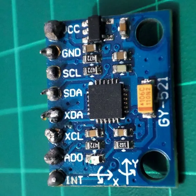
Pins Description of MPU6050
| VCC | 3.3V or 5V supply voltage |
| GND | Ground pin |
| SCL | SCL pin for I2C communication |
| SDA | SDA pin for I2C communication |
| XDA | For connecting another I2C device with MPU6050 |
| XCL | For connecting another I2C device with MPU6050 |
| AD0 | For changing the I2C address |
| INT | Interrupt pin |
ESP32 Bluetooth Classic: The project
Using the MPU6050 module and ESP32 we will read the 3 axes of angular velocity and 3 axes of acceleration. After gating these values will be sent the data to a Windows serial terminal software called Tera Term over ESP32 Bluetooth.
Component List for the project
| Component Name | Quantity | Purchase Links |
|---|---|---|
| ESP32 dev. Board | 1 | Amazon | AliExpress |
| MPU6050 | 1 | Amazon | AliExpress |
| Micro USB cable | 1 | Amazon | AliExpress |
Affiliate Disclosure: When you click on links to make a purchase, this can result in this website earning a commission.
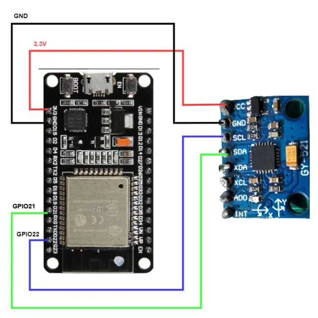
Connection Diagram between ESP32 and MPU6050
Connect GPIO21 (default SDA pin) of ESP32 with the SDA pin of MPU6050 and GPIO22 (default SCL pin) of ESP32 with the SCL pin of MPU6050. Also, connect MPU6050 VCC with ESP32 3.3V and MPU6050 GND with ESP32 GND.
Installing libraries for Arduino IDE
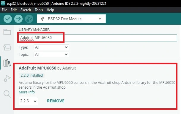
Go to your Arduino IDE. Go to tools>>manage libraries>>search for adafruit mpu6050. And install this library.
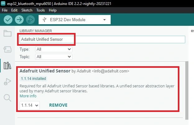
Again search for Adafruit Unified Sensor. Click install to install this library.
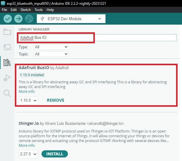
Finally, search for Adafruit Bus IO. And install this library.
Project Code
Arduino IDE .ino file
#include "BluetoothSerial.h"
#include "string.h"
#include <Adafruit_MPU6050.h>
#include <Adafruit_Sensor.h>
#include <Wire.h>

BluetoothSerial SerialBT;

#if !defined(CONFIG_BT_ENABLED) || !defined(CONFIG_BLUEDROID_ENABLED)
#error Bluetooth is not enabled! Please run `make menuconfig` to and enable it
#endif
Adafruit_MPU6050 mpu6050;
float x, y, z;
float yaw, pitch, roll;

String str_1;
String str_2;

void setup()
{
  SerialBT.begin("ESP32test");
  Serial.begin(115200);
  while (!Serial)
    delay(10); // will pause Zero, Leonardo, etc until serial console opens

  Serial.println("MPU6050 test!");

  // Try to initialize!
  if (!mpu6050.begin()) {
    Serial.println("Failed to find MPU6050 chip");
    while (1) {
      delay(10);
    }
  }
  Serial.println("MPU6050 Found!");
  mpu6050.setAccelerometerRange(MPU6050_RANGE_8_G);
  mpu6050.setGyroRange(MPU6050_RANGE_500_DEG);
  mpu6050.setFilterBandwidth(MPU6050_BAND_5_HZ);
  delay(1000);
}

void loop()
{
  mpu6050_read();
  BT_send_data();
  delay(1000);
}

void mpu6050_read(void){
  /* Get sensor events with the readings */
  sensors_event_t a, g, temp;
  mpu6050.getEvent(&a, &g, &temp);
  /* Read the 3 axis acceleration values */

  x=a.acceleration.x;
  y=a.acceleration.y;
  z=a.acceleration.z;

 /* Print the 3 axis acceleration values on serial monitor */
  Serial.print("X-Axis: ");
  Serial.println(x);
  Serial.print("Y-Axis: ");
  Serial.println(y);
  Serial.print("Z-Axis: ");
Serial.println(z);

/* Read the 3 axis angular velocity(gyroscope) values */

  yaw=g.gyro.x;
  pitch=g.gyro.y;
  roll=g.gyro.z;

/* Print the 3 axis angular velocity(gyroscope) values on serial monitor */
  Serial.print("YAW: ");
  Serial.println(yaw);
  Serial.print("PITCH: ");
  Serial.println(pitch);
  Serial.print("ROLL: ");
  Serial.println(roll);

}
void BT_send_data(void){
  str_1 = String(x)+"\t"+String(y)+"\t"+String(z);
  str_2 = String(yaw)+"\t"+String(pitch)+"\t"+String(roll);
  //send the string to bluetoth serial port
  SerialBT.print("Acceleration reading; ");
  SerialBT.println(str_1);
  SerialBT.print("Gyroscope readings: ");
  SerialBT.println(str_2);
}
How the Code works
#include "BluetoothSerial.h"
#include "string.h"
#include <Adafruit_MPU6050.h>
#include <Adafruit_Sensor.h>
#include <Wire.h>
First, include essential libraries. No need to install BluetoothSerial.h and string.h libraries because they are automatically set after the board selects. How you can install the rest of the libraries that are shown above.
BluetoothSerial SerialBT;
Adafruit_MPU6050 mpu6050;
Create two objects for Bluetooth communication and MPU6050 sensor reading.
float x, y, z;
float yaw, pitch, roll;
String str_1;
String str_2;
Declare 6 float-type variables to store MPU6050 sensor values and two strings to store acceleration and angular velocity (gyroscope) values.
SerialBT.begin("ESP32test");
  Serial.begin(115200);
  while (!Serial)
    delay(10); // will pause Zero, Leonardo, etc until serial console opens

  Serial.println("MPU6050 test!");

  // Try to initialize!
  if (!mpu6050.begin()) {
    Serial.println("Failed to find MPU6050 chip");
    while (1) {
      delay(10);
    }
}
Serial.println("MPU6050 Found!");
In the setup, function initialize the Bluetooth serial and set the baud rate 115200 of the serial monitor. Also, verify the correct I2C device or MPU6050 module using if (!mpu6050.begin()) this condition. When the device is found a found message will show on the serial monitor.
mpu6050.setAccelerometerRange(MPU6050_RANGE_8_G);
mpu6050.setGyroRange(MPU6050_RANGE_500_DEG);
mpu6050.setFilterBandwidth(MPU6050_BAND_5_HZ);
To calibrate the MPU6050 sensor these three lines are needed.
mpu6050_read();
BT_send_data();
delay(1000);
In the loop function, we call the 2 function. The first one mpu6050_read() is for reading the MPU6050 sensor values and shows these values on the serial monitor. The second one BT_send_data() is for publishing these sensor values in Tera Term software over ESP32 Bluetooth. These 2 function is explained below.
Mpu6050_read() function:
void mpu6050_read(void){
  /* Get sensor events with the readings */
  sensors_event_t a, g, temp;
  mpu6050.getEvent(&a, &g, &temp);
  /* Read the 3 axis acceleration values */

  x=a.acceleration.x;
  y=a.acceleration.y;
  z=a.acceleration.z;

 /* Print the 3 axis acceleration values on serial monitor */
  Serial.print("X-Axis: ");
  Serial.println(x);
  Serial.print("Y-Axis: ");
  Serial.println(y);
  Serial.print("Z-Axis: ");
  Serial.println(z);

/* Read the 3 axis angular velocity(gyroscope) values */

  yaw=g.gyro.x;
  pitch=g.gyro.y;
  roll=g.gyro.z;
/* Print the 3 axis angular velocity(gyroscope) values on serial monitor */
  Serial.print("YAW: ");
  Serial.println(yaw);
  Serial.print("PITCH: ");
  Serial.println(pitch);
  Serial.print("ROLL: ");
  Serial.println(roll);
}
First, a, g, and temp are the three sensors_event_t variables. sensors_event_t is a custom struct or data type defined in a library specific to the MPU6050 sensor, which encapsulates sensor data.
after that, the three-axis acceleration values are stored to x, y, and z respectively. And print these values on an Arduino IDE serial monitor.
similarly, yaw, pitch, and roll store the angular velocity(gyroscope) values and these values are printed on Serial monitor using Serial.println() function.
BT_send_data() Function:
void BT_send_data(void){
  str_1 = String(x)+"\t"+String(y)+"\t"+String(z);
  str_2 = String(yaw)+"\t"+String(pitch)+"\t"+String(roll);
  //send the string to bluetoth serial port
  SerialBT.print("Acceleration reading; ");
  SerialBT.println(str_1);
  SerialBT.print("Gyroscope readings: ");
  SerialBT.println(str_2);
}
This function is used for sending data to a serial terminal (EX:Tera Term) over esp32 Bluetooth. The first string(str_1) stores the three-axis Acceleration values as a string. Similarly, the second string(str_2) is responsible for storing three-axis Gyroscope values as a string. Finally, these two strings is send to a serial terminal over Bluetooth using SerialBT.print() function.
Uploading the Code to ESP32
To upload this code open your Arduino IDE. Create a new sketch and copy and paste the full code. Save the code. Go to Tools>>Board>>select ESP32 dev module. After selecting the right port hit the upload button of Arduino IDE. To know more about uploading see this article:
How to install ESP32 Board in Arduino IDE
Install Tera-Term
After uploading the code you need Tera-term software to see MPU6050 sensor values. Go to https://github.com/TeraTermProject/teraterm/releases and download and install Tera-term.
Output of the Code
After uploading the code open your Arduino IDE serial monitor and set the baud rate to 115200. And here is the result you can see like this.
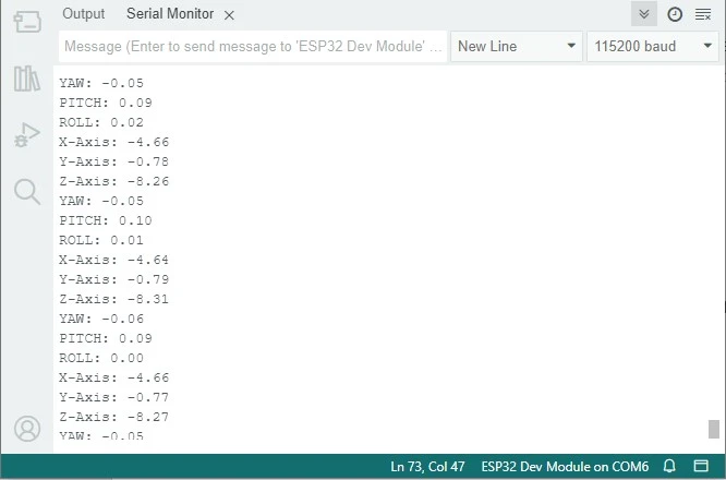
You can see the acceleration and gyroscope values of the MPU6050 module.
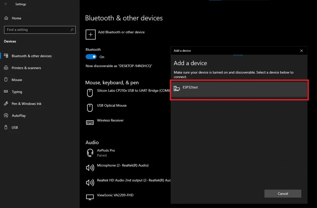
Now, to see Bluetooth values first you need to pair your ESP32 Bluetooth with your Windows PC. To do that go to Settings>>Devices>>Bluetooth and others devices. Click add Bluetooth or devices and click Bluetooth and wait some seconds.
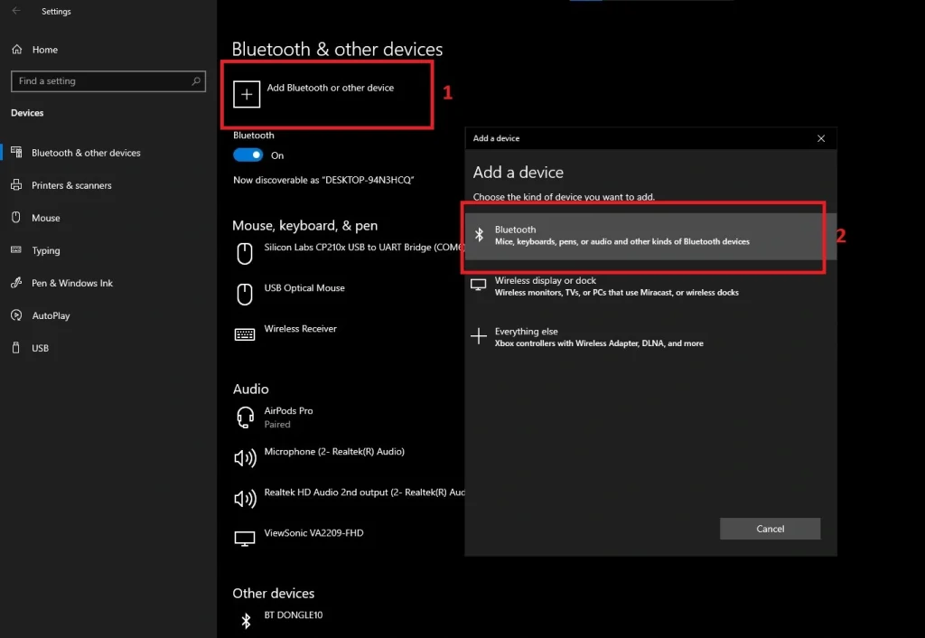
After that you will see a Bluetooth device named ESP32test. Click on ESP32test and paired this device.
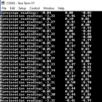
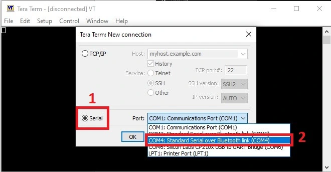
Now open your Tera Term software. Select the serial and select the right Bluetooth port. In my case this was COM3.
And here is the result: