This tutorial will guide you on storing and retrieving values from the ESP32’s flash memory (similar to EEPROM) using the Arduino IDE. Data stored in the flash memory persists even after the ESP32 is reset or powered off. We will also build a small project to save the last state of a GPIO pin of ESP32.
ESP32 EEPROM Basics
On microcontrollers (like Arduino Uno), EEPROM (Electrically Erasable Programmable Read-Only Memory) is generally used to store a small amount of data which is required to be persisted even if the device loses power, in other words, non-volatile memory. But, ESP32 doesn’t contain a dedicated EEPROM like some other microcontrollers have. Instead, it uses some part of its flash memory to emulate EEPROM-like behavior. The mentioned flash memory is based on NAND flash technology due to which it will not lose data as long as we are providing supply voltage.
Use of ESP32 EEPROM
Calibration Settings: This allows sensors and devices to behave in accordance with the current environmental conditions or as configured to satisfy individual users’ preferences. EEPROM on the ESP32 implies that multiple bytes can be kept for calibration, and this data is saved even when the power is switched off. For example, libraries such as MPU-9250 include features that allow calibration data to be kept in the EEPROM, saving a significant amount of frequency calibration when the system is restarted.
User Preferences: It enriches the usage of the device by providing the ability to configure a behavior of the device such as volume control or the screen brightness. To help cope with this issue, the ESP32 EEPROM library can be used to store user preferences.
Application State: The ability to persist the application state through resets is valuable for those apps that need to keep the continuity such as smart home applications, applications for games, etc. For instance, in the event of a reboot, an LED state must be preserved in order to be restored; this can be written into the EEPROM.
Flash Memory
Let me explain this in a bit of detail before diving deeper into the details of the ESP32 EEPROM and its vital role in the embedded system industry to help you understand ESP32 EEPROM, it is crucial first to understand Flash Memory on ESP32. An electrically erasable and programmable non-volatile memory type of semiconductor is created by it. Furthermore, it could read a more advanced and fixable version. Using NOR gate on its architecture and it is Bit-Wise Erasable Full form of Flash Memory.
- Storing the last state of a variable.
- Keeping settings.
- Tracking how many times an appliance was used.
- Storing any data that needs to be saved permanently.
EEPROM Library
The ESP32 EEPROM library is one of the important and typical libraries for any developer engaging in the development of the ESP32 microcontroller because it facilitates storage of the non-volatile data. Before using this, you must have the ESP32 board added to your Arduino IDE. If you are not familiar with configuring your ESP32 in Arduino IDE, then begin the Arduino IDE, and navigate to File > Preferences. In the “Additional Board Manager URLs” field, add the URL https://dl.espressif.com/dl/package_esp32_index.json. If you have other URLs, list them in comma comma-separated manner.
Next, go to Tools > Board > Boards Manager, search for “ESP32,” and install “ESP32 by Espressif Systems.” Next, click on Tools and then choose your ESP32 board model, for instance, ESP32 DEVKIT. Then, with the help of a USB cable, connect the ESP32 board to your personal computer. At last, click on Tools then on Port, to choose the right COM port of the ESP32 board.
In order to read and write data into the ESP32 flash memory when working in the Arduino IDE, you can only use the EEPROM. In fact, the process is almost identical to how it was done with the Arduino device. If you’re already familiar with using EEPROM on Arduino, you’ll find that working with it on the ESP32 is nearly the same and easy.
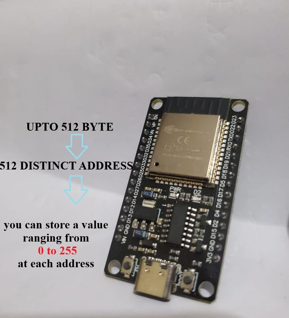
Employing the EEPROM library with the ESP32, one can work with a total of 512 bytes of flash memory. This gives you 512 addresses, and at each address resides a value that is a number between 0-255.

EEPROM Write
The ‘EEPROM.write()’ function in the ESP32 EEPROM library is used to store a byte of data (save the data, and the value) at a specified memory address in the flash memory.
Function Signature as follows:
void EEPROM.write(int address, uint8_t value);
To write data, call the ‘EEPROM.write()’ function with the desired address and value. For example:
EEPROM.write(0, 9); // Writes the value 9 to address 0
Afterward:
EEPROM.commit(); // Saves changes made by write ()
After calling ‘EEPROM.write()’ you must call ‘EEPROM.commit()’ to ensure that the changes are saved permanently to flash memory. This step is crucial because it finalizes the write operation.
EEPROM Read
The ‘EEPROM.read()’ function in the ESP32 EEPROM library is used to retrieve a byte of data from a specified memory address in the flash memory. This function is essential for reading previously stored data, allowing applications to access configurations, settings, or other important information that needs to persist across power cycles. Function Signature as follows:
EEPROM.read(address);
For instance, to read the byte previously saved at address 0, use:
EEPROM.read(0);
This would return 9, the value we stored at address 0.
ESP32 EEPROM Tutorial: The Project
In this project, we will illustrate how to save data in the flash memory of ESP32 by saving the state of an output which is an LED. Consider the following scenario: Suppose you are commanding a lamp with the ESP32. You flip the switch of the lamp, however, after that ESP32 loses power for some reason. If the power is switched on the lamp is off since it has no memory of what it was when the power was switched off.

By writing and reading values from the ESP32’s EEPROM, we do guarantee that the lamp will remember its last state so it can immediately turn back on in case of power failure.
Implementation Steps:
1. Save Lamp State: Synchronize flash memory with the current state of the lamp every time it toggles.
2. Check State on Startup: To load the last saved data in the flash the program should start with the condition to read the data from the flash memory.
3. Restore State: Depending on the state that has been retrieved, the switch operation of the lamp is to be done; that is, to turn it ON OR OFF.

Component List
| Name of Component | Quantity | Purchase Link |
| ESP32 DEVKIT Board | 1 | Amazon |
| 5mm LED | 1 | Amazon |
| 330, 10K Ohm Resistor | 1 | Amazon |
| Pushbutton | 1 | Amazon |
| Breadboard | 1 | Amazon |
| Jumper Wires set | 1 | Amazon |
Schematic Circuit
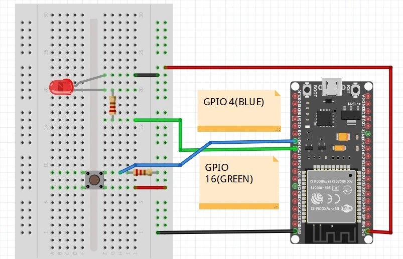
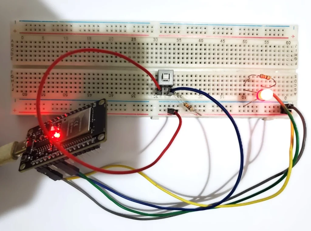
Connect a pushbutton and an LED to the ESP32, as the schematic picture below indicates.

Code
Copy the code below into the Arduino IDE and upload it to your ESP32. Ensure that you have the correct board and COM port selected.
// Import library for flash memory operations
#include <EEPROM.h>

// Define the EEPROM size for accessing 1 byte
#define EEPROM_SIZE 1

// Pin definitions remain unchanged:
const int inputButtonPin = 4;    // Pushbutton pin
const int outputLEDPin = 16;     // LED pin

// Variables for tracking states:
int stateOfLED = HIGH;       // Current LED state (ON/OFF)
int inputButtonState;        // Current state of the button
int lastInputState = LOW;    // Previous button state

// Timing variables for debouncing:
unsigned long debounceStartTime = 0;
unsigned long debounceTime = 50;      // Debounce delay

void setup() {
  Serial.begin(115200);

  // Initialize EEPROM memory size
  EEPROM.begin(EEPROM_SIZE);

  pinMode(inputButtonPin, INPUT);
  pinMode(outputLEDPin, OUTPUT);

  // Load and set the last saved LED state from EEPROM
  stateOfLED = EEPROM.read(0);
  digitalWrite(outputLEDPin, stateOfLED);
}

void loop() {
  // Read button's current state
  int currentButtonReading = digitalRead(inputButtonPin);

  // Detect button state changes:
  if (currentButtonReading != lastInputState) {
    debounceStartTime = millis();
  }

  // Check after debounce time:
  if ((millis() - debounceStartTime) > debounceTime) {
    if (currentButtonReading != inputButtonState) {
      inputButtonState = currentButtonReading;

      // Toggle LED state if button is pressed
      if (inputButtonState == HIGH) {
        stateOfLED = !stateOfLED;
      }
    }
  }

  // Save the current state for next loop iteration
  lastInputState = currentButtonReading;

  // If the LED state changes, update and save to EEPROM
  if (digitalRead(outputLEDPin) != stateOfLED) {
    Serial.println("LED state updated");
    digitalWrite(outputLEDPin, stateOfLED);
    EEPROM.write(0, stateOfLED);
    EEPROM.commit();
    Serial.println("Saved to EEPROM");
  }
}
RAW CODE:
https://github.com/ArifRahmanEEE/IOT/blob/Arduino/ESP32_EEPROm/ESP32_EEPROm.ino
How the Code Works
This code changes the LED state every time when a button is clicked. However, this code has a unique feature: It does this by preserving the last LED state even when the ESP32 is reset or when power is switched off. Now let’s discuss what you can do to ensure the ESP32 remembers the previous state of a GPIO.
First of all, the EEPROM library provides functions for reading from and writing to the EEPROM (flash memory) of the ESP32.
#include <EEPROM.h>’
Size Definition
The size of the EEPROM to be used in this program. Here, we allocate 1 byte for storing the LED state.
#define EEPROM_SIZE 1
Pin Definitions
GPIO pins are used for the input button and output LED. The button is connected to pin 4, and the LED is connected to pin 16
const int inputButtonPin = 4;    // Pushbutton pin
const int outputLEDPin = 16;     // LED pin
State Variables
‘stateOfLED’: Stores the current state of the LED (either HIGH for ON or LOW for OFF).
‘inputButtonState’: Holds the current state of the button.
‘lastInputState’: Keeps track of the previous state of the button for detecting changes.
// Variables for tracking states:
int stateOfLED = HIGH;       // Current LED state (ON/OFF)
int inputButtonState;        // Current state of the button
int lastInputState = LOW;    // Previous button state
Timing Variables for Debouncing
‘debounceStartTime’: Records the time when a button state change is detected.
‘debounceTime’: Sets a delay (in milliseconds) to prevent false triggering due to mechanical bouncing when pressing the button.
// Timing variables for debouncing:
unsigned long debounceStartTime = 0;
unsigned long debounceTime = 50;      // Debounce delay
Setup Function
Calls EEPROM.begin(EEPROM_SIZE) to prepare EEPROM for use.
EEPROM.begin(EEPROM_SIZE);
Sets the button pin as an input and the LED pin as an output.
pinMode(inputButtonPin, INPUT);
pinMode(outputLEDPin, OUTPUT);
Reads the last saved LED state from EEPROM at address 0 and sets it accordingly, ensuring that the LED reflects its previous state when power was lost.
// Load and set the last saved LED state from EEPROM
stateOfLED = EEPROM.read(0);
digitalWrite(outputLEDPin, stateOfLED);
Loop Function
The loop () continues by checking if the pushbutton was pressed and changing the ledState variable each time. To avoid false positives, we utilize a timer. This code snippet is based on the Arduino IDE’s pushbutton debounce sketch example
// Read button's current state
  int currentButtonReading = digitalRead(inputButtonPin);

  // Detect button state changes:
  if (currentButtonReading != lastInputState) {
    debounceStartTime = millis();
  }

  // Check after debounce time:
  if ((millis() - debounceStartTime) > debounceTime) {
    if (currentButtonReading != inputButtonState) {
      inputButtonState = currentButtonReading;

      // Toggle LED state if button is pressed
      if (inputButtonState == HIGH) {
        stateOfLED = !stateOfLED;


  // Save the current state for next loop iteration
  lastInputState = currentButtonReading;

  // If the LED state changes, update and save to EEPROM
  if (digitalRead(outputLEDPin) != stateOfLED) {
    Serial.println("LED state updated");
    digitalWrite(outputLEDPin, stateOfLED);
    EEPROM.write(0, stateOfLED);
    EEPROM.commit();
    Serial.println("Saved to EEPROM");
Read Button State:
Reads the current state of the button using ‘digitalRead(inputButtonPin)’.
Debouncing Logic:
If a change in button state is detected, it records the time. After waiting for ‘debounceTime’, it checks if the button’s current reading has changed since it was last read. If it has changed and indicates that the button is pressed ‘(inputButtonState == HIGH)’, it toggles ‘stateOfLED’.
Update Last State:
Updates ‘lastInputState’ with ‘currentButtonReading’ for use in the next loop iteration.
Update LED State:
If there’s a change in ‘stateOfLED’, it updates the physical LED and writes this new state to EEPROM at address 0. Calls ‘EEPROM.commit()’ to ensure that changes are saved permanently. Prints messages to Serial Monitor for debugging purposes.
Illustration
Once uploading the code to your ESP32, hit the push button to turn the LED on and off. After resetting or turning off the power, the ESP32 should maintain the previous LED status.

Conclusion
In this project, we took the ESP32 and looked at how to implement EEPROM to save the last state of a GPIO pin so that a system can remember where it left even after a reset or power outage. This technique is very effective when used in practical IoT applications since persistent state storage is often important for both the usability and applicability of the IoT application. As will be seen when implementing the simple debounce mechanism below, the EEPROM library can be used to build very frugal and solid solutions for small embedded systems.
