
In a world of connectivity, the demand for faster, more reliable internet access is ever-growing. That’s why IoT devices depend not only on WiFi or GSM (2G). 4G LTE communication has become popular on IoT devices because 4G LTE communication is faster and more reliable than GSM in a remote area. In this tutorial, we will cover interfacing between the ESP32 and SIM7600 4G LTE modules, and send some data to the ThingSpeak server using the SIM7600G module.
You may also like reading:
- IoT Based Energy Monitoring System using ESP32 and Firebase
- ESP32 LoRaWAN Gateway tutorial with Sensor Node
Introduction
You may already know about SIM800, which is a 2G module with a maximum 85.6 kbps data transfer rate. But day-by-day data is bigger, and we need a high-speed module that can transfer our data within a millisecond. SIM7600 is an LTE-capable SIM module that has up to 10Mbps downlink rate and 5Mbps uplink rate.
Also, it supports AT commands, so you can call and send messages using the SIM7600 module. In this article, we only focus on sending data to an IoT platform such as ThingSpeak using SIM7600.
Features of SIM7600G Module
- wireless communication: LTE-TDD/ LTE-FDD/HSPA+/GSM/GPRS/EDGE etc.
- Data speed: maximum 10Mbps downlink rate and 5Mbps uplink rate.
- GPRS, 4G LTE support
- AT command capability
- Interfaces: UART, USB, I2C, GPI
SIM7600G Pinout
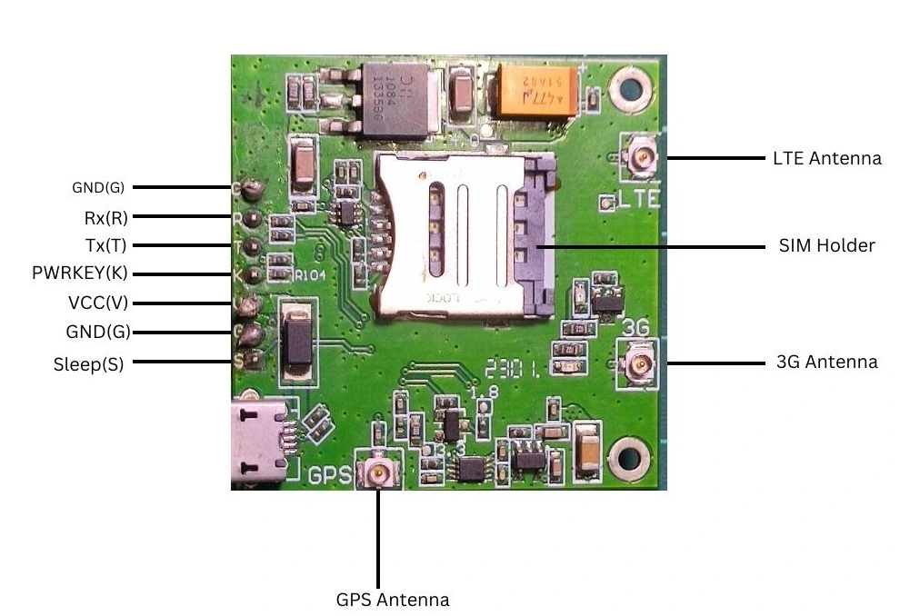
| Pin Symbol | Pin Description | Comment |
|---|---|---|
| G | Ground | Connect with microcontroller ground pin |
| R | Rx | Connect with microcontroller Tx pin |
| T | Tx | Connect with microcontroller Rx pin |
| K | Power key/reset pin | Connect with microcontroller any GPIO pin |
| V | Vcc | Connect with 5V power supply (recommended to use separate power supply) |
| S | Sleep |
Dallas DS18B20 Temperature Sensor
In this article, we will send some temperature sensor data to the ThingSpeak server. We are going to use a Dallas DS18B20 temperature sensor. So, you have to know a little bit about the Dallas temperature sensor.
The Dallas temperature sensor is a digital sensor. You can take readings from this sensor by connecting the Vcc, GND, and data pins to your microcontroller.
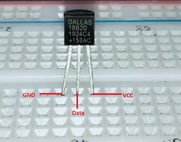
DS18B20 Temperature Sensor Pinout
- GND: Connect the Ground pin with the power source ground pin
- Data: Connect data pin with any digital pin of the microcontroller
- VCC: Connect VCC pin with 3.3V-5V of the power source
Sending data to the ThingSpeak server using the SIM7600G module: The Project
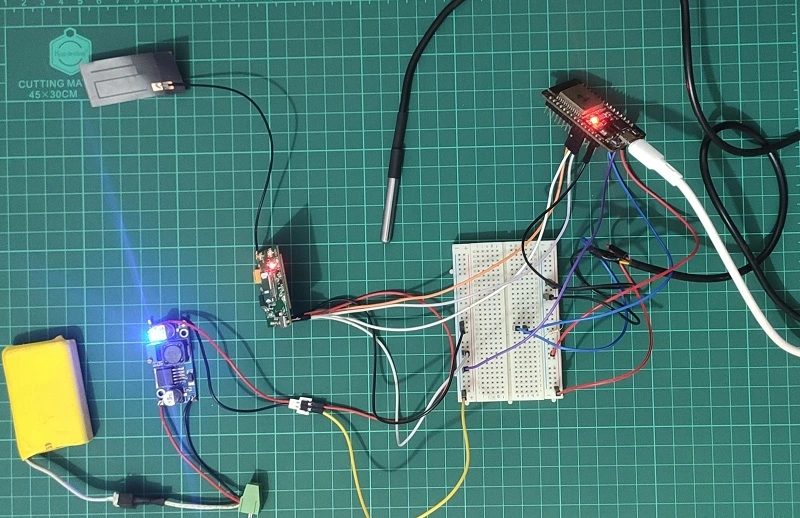
In this section of the tutorial, we will build a small real-world project by using ESP32 and SIM7600G 4G LTE module. We will read temperature data from a sensor called Dallas DS18B20 and send the temperature data to a popular open IoT platform called ThingSpeak by using the SIM7600G module.
Component List
| Component Name | Quantity | Purchase Links |
|---|---|---|
| ESP32 Dev. Board | 1 | Amazon.com | AliExpress |
| SIM7600G module | 1 | Amazon.com | AliExpress |
| Dallas DS18B20 sensor | 1 | Amazon.com | AliExpress |
| 4.7K resistor | 1 | Amazon.com | AliExpress |
| 9V battery | 1 | Amazon.com | AliExpress |
| DC-DC converter | 1 | Amazon.com | AliExpress |
Affiliate Disclosure: When you click on links to make a purchase, this can result in this website earning a commission.
Circuit Diagram
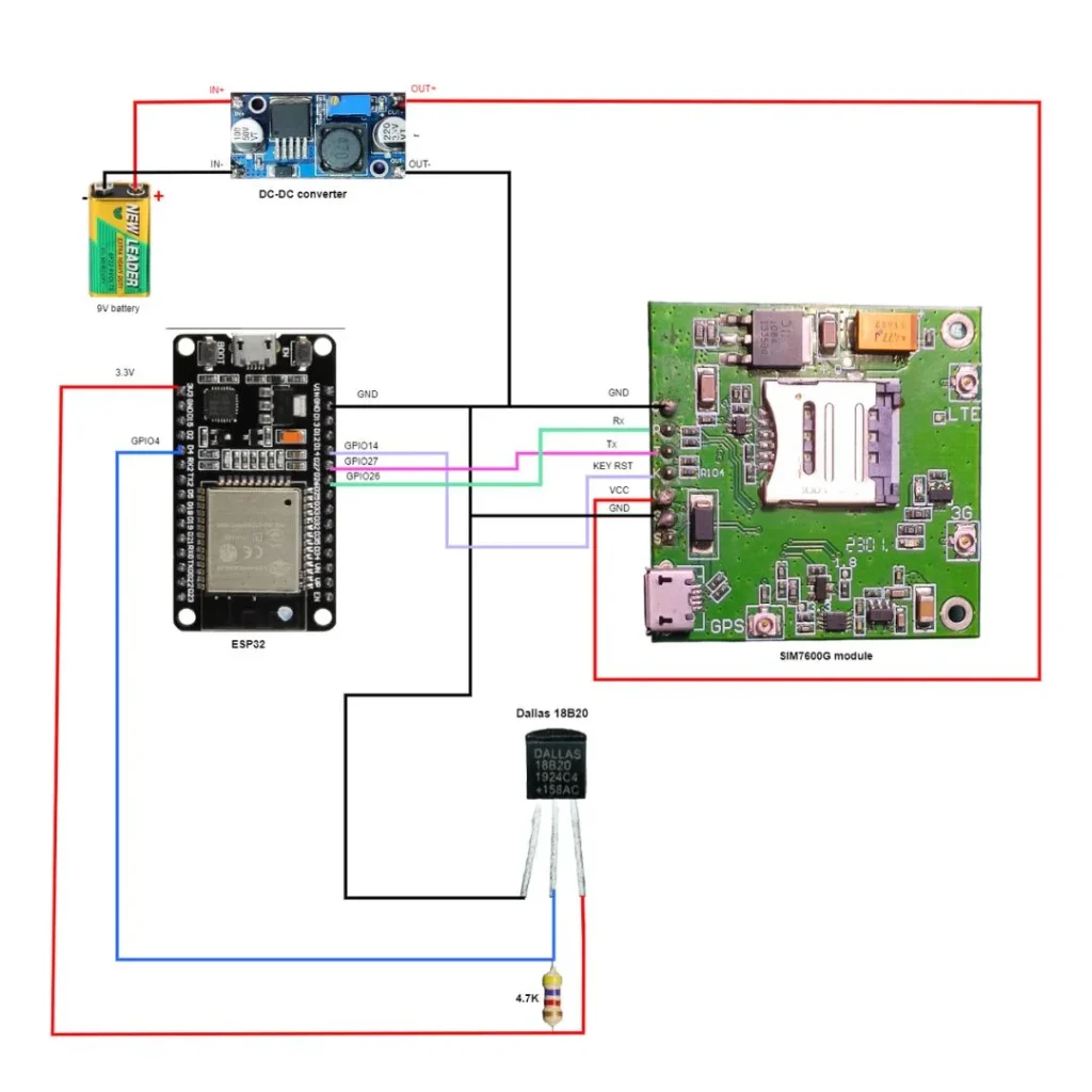
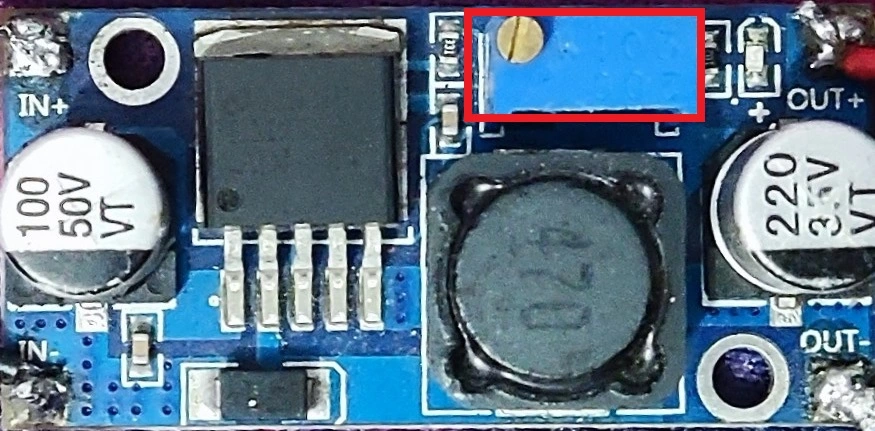
Note: you can adjust the voltage of the DC-DC converter by rotating the knob of the potentiometer of the DC-DC voltage.
Creating a ThingSpeak Channel
Step 01: Go to https://thingspeak.com/ and sign up with your email. After signing up you will see this window.

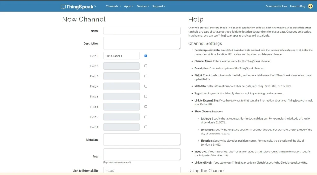
Step 02: Click Channels then click New Channels and you will see this window.
Step 03: Now type your channel name and click save the channel.
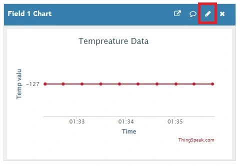
Step 04: After saving your channel you will see this window. Click the edit icon.
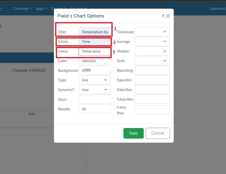
Step 05: Name the title, X-Axis, and Y-Axis name of your graph.
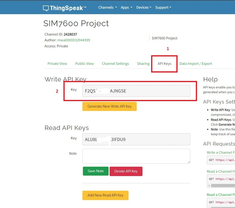
Step 06: After that, from your channel page, go to API keys and copy your API key in a note. Later, we will need this API key.
Step 07: Your ThingsPeak graph is ready. When data comes to the ThingSpeak server you will see your data to Channels>>my channel>>the channel that you want to see on the ThingSpeak website.
Now move into the coding part.
Installing Some Arduino IDE Libraries for the Project
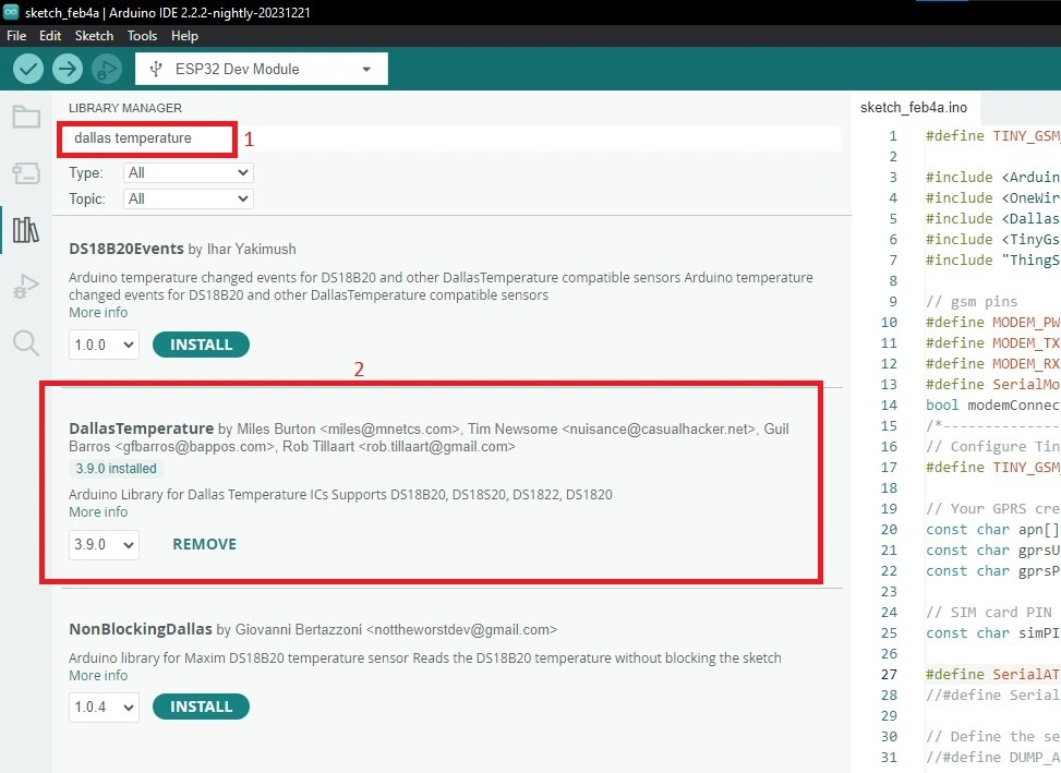
Step 01: Open your Arduino IDE and go to Tools>>Manage Libraries>>and search “Dallas temperature”. and install this library.
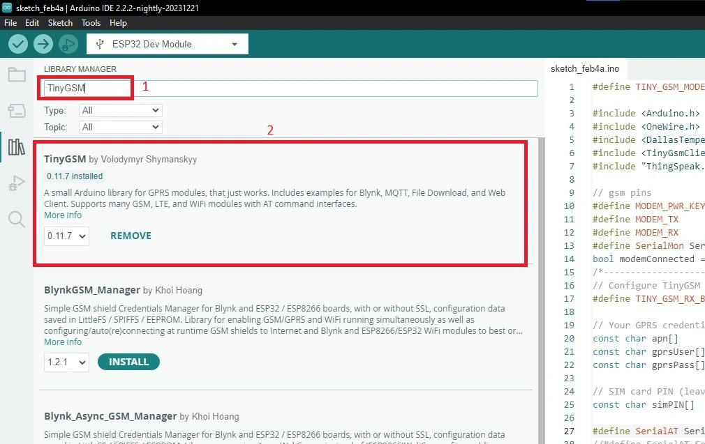
Step 02: Again go to Tools>>Manage Libraries>>and search “TinyGSM” and install this library.
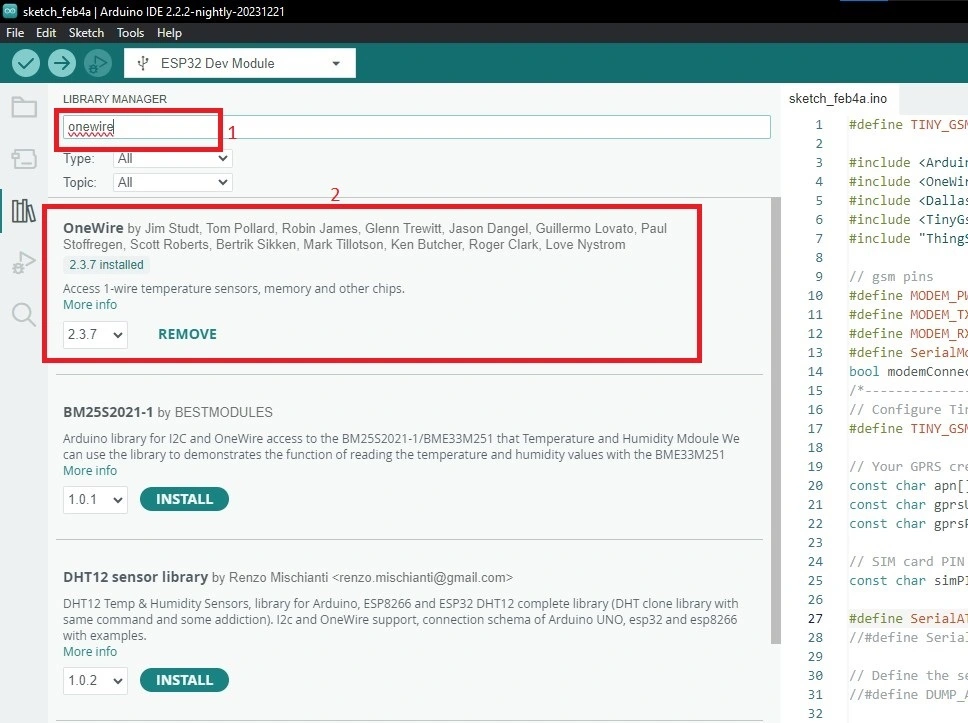
Step 03: Again search “onewire” and install this library.
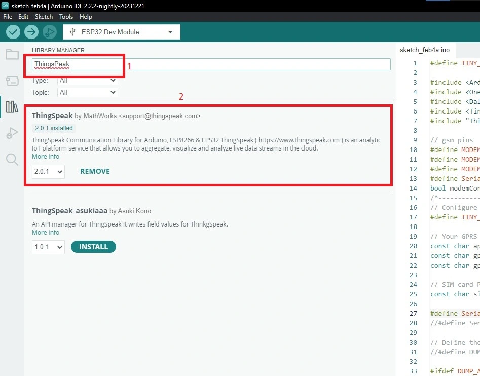
Step 04: Finally search “ThingSpeak” and install this library.
Code Explanation
This Arduino code is designed to interface a SIM7600 GSM module and a DS18B20 temperature sensor with ESP32, transmitting temperature data to the ThingSpeak platform using the TinyGSM library. Let’s break down the main components and functionalities of the code:
#define TINY_GSM_MODEM_SIM7600
In this project we are using SIM7600G GSM module so at the very beginning you must define what kind of SIM module you will use in your project. That’s why I have written this line.
#include <Arduino.h>
#include <OneWire.h>
#include <DallasTemperature.h>
#include <TinyGsmClient.h> //author: Volodymyr Shymanskyy
#include "ThingSpeak.h"
These lines are written to include all the libraries that we are going to use.
// gsm pins
#define MODEM_PWR_KEY        14
#define MODEM_TX            26
#define MODEM_RX             27
Define 3 pins of ESP32 to control the SIM7600G module. The first pin is for the modem reset pin. The 2nd and 3rd pins are TX and RX pins respectively. In this project, we use software serial of esp32 .
bool modemConnected = false;
A flag indicating whether the GSM module is connected.
// Your GPRS credentials (leave empty, if not needed)
const char apn[]      = "internet"; // APN (example: airtelgprs.com)
const char gprsUser[] = ""; // GPRS User
const char gprsPass[] = ""; // GPRS Password
GPRS credentials, such as Access Point Name (APN), GPRS username, password, and SIM card PIN.
#define SerialAT Serial1
As said earlier we use software serial in this project for this reason we define SerialAT as Serial1.
const int oneWireBus = 4;
float temperatureC;
OneWire oneWire(oneWireBus);
DallasTemperature DS18B20(&oneWire);
These lines for reading temperature sensor data. The first line defines which pin of ESP32 is used to read temperature sensor data. In my case it was GPIO4. The second line takes a variable that stores temperature data. 3rd and 4th lines are objects for interfacing with the DS18B20 temperature sensor.
TinyGsmClient client(modem);
TinyGsm client object for Internet connection.
unsigned long Channel_Number = 1;
const char * APIKey = "F2QS29SMIPAJNGSE";
ThingSpeak channel number and API key for sending data.
uint32_t tm = 0;
Variable to store the timestamp for sending data at regular intervals.
SerialMon.begin(115200);
delay(10);
DS18B20.begin();
In the setup function set the serial monitor baud rate to 115200 and initialize the Dallas DS18B20 temperature sensor.
// Set modem reset, enable, power pins
  pinMode(MODEM_PWR_KEY, OUTPUT);
  digitalWrite(MODEM_PWR_KEY, LOW);
  delay(500);
  digitalWrite(MODEM_PWR_KEY, HIGH);

  // Set GSM module baud rate and UART pins
  //SerialAT.begin(115200, SERIAL_8N1, MODEM_RX, MODEM_TX, false);
  SerialAT.begin(115200, SERIAL_8N1, MODEM_RX, MODEM_TX, false);
  //TinyGsmAutoBaud(SerialAT, 9600, 115200);
  delay(1000); //delay 3s to 1s edited


  // Restart SIM7600 module, it takes quite some time
  // To skip it, call init() instead of restart()
  SerialMon.println("Initializing modem...");
  modem.restart();
These lines are for initializing the SIM7600G module. The first few lines are for enabling reset pin to reset modem. Then set the baud rate of the modem and also set RX TX of the modem. We need to restart the modem in the setup function using modem.restart() function.
ThingSpeak.begin(client);
Initializes the ThingSpeak library with the TinyGsm client for Internet connection.
if (!modemConnected) {
    if (!modem.init()) {
      Serial.println("Failed to restart modem, delaying 10's and retrying");
      delay(500);
      return;
    }
    Serial.print(F("Waiting for network..."));
    if (!modem.waitForNetwork()) {
        Serial.println(" fail");
        delay(500);
        return;
    }
    Serial.println("Network Connected!");

    Serial.print(F("Connecting to "));
    Serial.print(apn);
    if (!modem.gprsConnect(apn, gprsUser, gprsPass)) {
        Serial.println(" fail");
        delay(500);
        return;
    }

    modemConnected = true;
    Serial.println("Internet Connected!");
  }
These lines are checked if the GSM module is not connected. If not connected, it attempts to establish a connection to the GSM network.
DS18B20.requestTemperatures();
temperatureC = DS18B20.getTempCByIndex(0);
Serial.print(temperatureC);
Serial.println("ºC");
These lines are for reading temperature data from the DS18B20 sensor. Reads the temperature in degrees Celsius from the sensor. Prints the temperature in the Serial Monitor.
 if((millis() - tm) > 10000)
  {
    int htpp_code = ThingSpeak.writeField(Channel_Number, 1, temperatureC, APIKey);
    if(htpp_code == 200){
      Serial.println("Data send successfully.");
    }
    else{
      Serial.println("HTTP Error. HTTP error code " + String(htpp_code));
    }
    tm = millis();
  }
After reading sensor data, we will send this data to the ThingsPeak server every 10 seconds. We check the HTTP code because we know that if the code is 200, this means the data is successfully sent. Using this condition, we can easily detect whether our data is sent or not.
Full Code
Arduino IDE .ino file
#define TINY_GSM_MODEM_SIM7600       // Modem is SIM7600  TINY_GSM_MODEM_SIM7600g

#include <Arduino.h>
#include <OneWire.h>
#include <DallasTemperature.h>
#include <TinyGsmClient.h> //author: Volodymyr Shymanskyy
#include "ThingSpeak.h"

// gsm pins
#define MODEM_PWR_KEY        14
#define MODEM_TX            26
#define MODEM_RX             27
#define SerialMon Serial
bool modemConnected = false;
/*--------------------- GSM AND THIBKSBOARD CODE START -------------------------------*/
// Configure TinyGSM library
#define TINY_GSM_RX_BUFFER   1024  // Set RX buffer to 1Kb

// Your GPRS credentials (leave empty, if not needed)
const char apn[]      = "internet"; // APN (example: airtelgprs.com)
const char gprsUser[] = ""; // GPRS User
const char gprsPass[] = ""; // GPRS Password

// SIM card PIN (leave empty, if not defined)
const char simPIN[]   = "";

#define SerialAT Serial1
//#define SerialAT SerialGsm

// Define the serial console for debug prints, if needed
//#define DUMP_AT_COMMANDS

#ifdef DUMP_AT_COMMANDS
#include <StreamDebugger.h>
StreamDebugger debugger(SerialAT, SerialMon);
TinyGsm modem(debugger);
#else
TinyGsm modem(SerialAT);
#endif

// I2C for SIM800 (to keep it running when powered from battery)
//----TwoWire I2CPower = TwoWire(0);

// GPIO where the DS18B20 is connected to
const int oneWireBus = 4;
// Variable to hold temperature readings
float temperatureC;
// Setup a oneWire instance to communicate with any OneWire devices
OneWire oneWire(oneWireBus);
// Pass our oneWire reference to Dallas Temperature sensor
DallasTemperature DS18B20(&oneWire);

// TinyGSM Client for Internet connection
TinyGsmClient client(modem);

// TinyGSM Client for Internet connection
unsigned long Channel_Number = 1;
const char * APIKey = "Write_your_API";  //copy and past your api key of thingspeak

uint32_t tm = 0;

/*----------------- GSM AND THIBKSBOARD CODE END-----------------------------------*/

void setup() {
  // Set console baud rate
  SerialMon.begin(115200);
  delay(10);
  DS18B20.begin();

  // Set modem reset, enable, power pins
  pinMode(MODEM_PWR_KEY, OUTPUT);
  digitalWrite(MODEM_PWR_KEY, LOW);
  delay(500);
  digitalWrite(MODEM_PWR_KEY, HIGH);

  // Set GSM module baud rate and UART pins
  //SerialAT.begin(115200, SERIAL_8N1, MODEM_RX, MODEM_TX, false);
  SerialAT.begin(115200, SERIAL_8N1, MODEM_RX, MODEM_TX, false);
  //TinyGsmAutoBaud(SerialAT, 9600, 115200);
  delay(1000); //delay 3s to 1s edited

  // Restart SIM7600 module, it takes quite some time
  // To skip it, call init() instead of restart()
  SerialMon.println("Initializing modem...");
  modem.restart();
  //modem.init();
  // use modem.init() if you don't need the complete restart

  // Unlock your SIM card with a PIN if needed
  if (strlen(simPIN) && modem.getSimStatus() != 3 ) {
    modem.simUnlock(simPIN);
  }
  ThingSpeak.begin(client);  // Initialize ThingSpeak
  tm = millis();
}

void loop() {
  if (!modemConnected) {
    if (!modem.init()) {
      Serial.println("Failed to restart modem, delaying 10's and retrying");
      delay(500);
      return;
    }
    Serial.print(F("Waiting for network..."));
    if (!modem.waitForNetwork()) {
        Serial.println(" fail");
        delay(500);
        return;
    }
    Serial.println("Network Connected!");

    Serial.print(F("Connecting to "));
    Serial.print(apn);
    if (!modem.gprsConnect(apn, gprsUser, gprsPass)) {
        Serial.println(" fail");
        delay(500);
        return;
    }
    modemConnected = true;
    Serial.println("Internet Connected!");
  }

  DS18B20.requestTemperatures();
  temperatureC = DS18B20.getTempCByIndex(0);
  Serial.print(temperatureC);
  Serial.println("ºC");

  if((millis() - tm) > 10000)
  {
    int htpp_code = ThingSpeak.writeField(Channel_Number, 1, temperatureC, APIKey);
    if(htpp_code == 200){
      Serial.println("Data send successfully.");
    }
    else{
      Serial.println("HTTP Error. HTTP error code " + String(htpp_code));
    }
    tm = millis();
  }
  delay(1000);
}
Uploading the Code
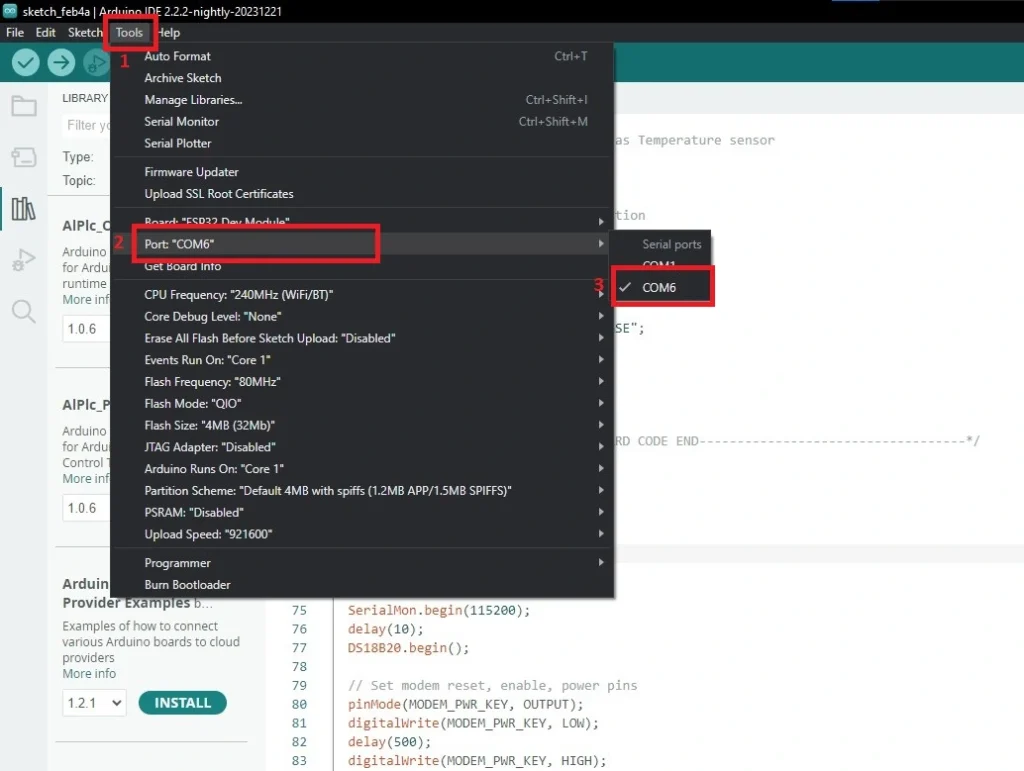
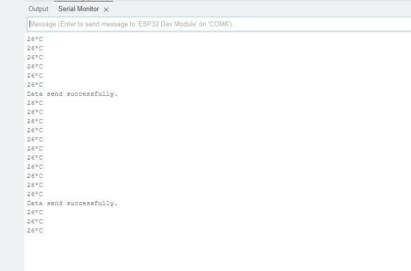
Open your Arduino IDE copy the full code and paste it to a new sketch of your Arduino IDE. Save your sketch. Now connect your ESP32 to your PC. Go to tools>>Port>>select the right port. In my case it was COM6.
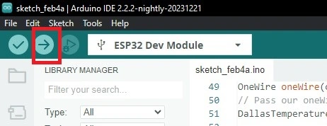
After that hit the upload button and wait for uploading.
Result
After uploading open the serial monitor of your Arduino IDE. Select the baud rate 115200. Now, You can see the temperature reading of the sensor. And also see these data a successful data send message that indicates that the data is successfully published to ThingsPeak server.
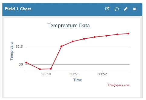
Now go to the ThingsPeak website and go to private view and you will find a graph.
Conclusion
This article will help you interface between the ESP32 and SIM7600 modules. Also, you will be able to send data to an IoT server using the SIM7600 module, and this experience will help you in your further IoT projects.