
This is a comprehensive guide on Ethernet communication using Wiznet W5500 module. We will demonstrate how to use Wiznet W5500 IC to send messages to a computer as well as receive messages from the computer. To help you get a hold of this, we will also build an example project on a very popular board from STM32, known as “Bluepill” (STM32F103C8T6).
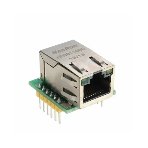
Understanding the W5500 Wiznet Module
The WIZnet module is a compact Ethernet networking module based on WIZnet’s W5x00 series chips (e.g., W5500), providing a hardwired TCP/IP stack for easy integration with microcontrollers via SPI. It allows stable, low-resource Ethernet communication with support for multiple sockets, ideal for IoT and embedded systems needing reliable wired networking.
The WIZnet module works by offloading all TCP/IP networking tasks onto its built-in hardware chip (like W5500), so your microcontroller just sends and receives data over SPI. The microcontroller tells the WIZnet chip to open a socket, connect to a server (or listen), and send/receive data. The chip handles all the protocol layers (TCP, UDP, IP, etc.) internally, so your code stays simple and fast, without needing a software TCP/IP stack.
To understand more about how this module works, here is a datasheet for the module
Sending and Receiving Messages via W5000: The Project
We will be sending data from the PC to the MCU and vice versa. The communication will be in pooling mode. We will be working on a pre-established library of this module and try to interact using the STM32 microcontroller. Before proceeding, please download apps like hercules to be able to communicate with the chip via ethernet.
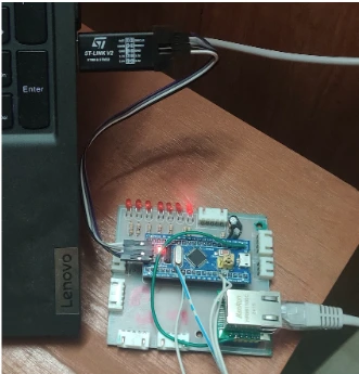
Below, there is a hardware prototype. There are additional features and functions.
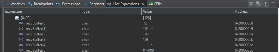
In our project, we will be storing incoming data from the PC to the MCU in a buffer. It will look like this:
Component List
| Component Name | Quantity | Purchase Link |
| STM32F103C8T6 | 1 | Amazon | AliExpress |
| Wiznet W5500 | 1 | Amazon | AliExpress |
| ST-Link V2 | 1 | Amazon | AliExpress |
| Ethernet cable RJ-45 | 1 | Amazon | AliExpress |
| Breadboard | 1 | Amazon | AliExpress |
| LED | 1 | Amazon | AliExpress |
| Resistor (1k Ohm) | 1 | Amazon | AliExpress |
For troubleshooting, some beneficial test equipment
| Equipment Name | Purchase Link |
| Best Oscilloscope for Professionals | Amazon |
| Best Oscilloscope for Beginners and Hobbyists | Amazon |
| Logic Analyzer | Amazon |
| Best Budget Multimeter | Amazon |
| Adjustable Power Supply | Amazon |
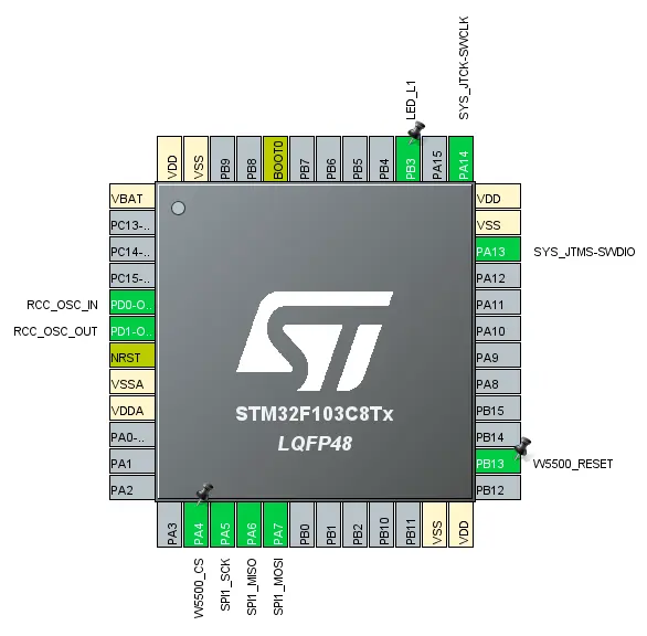
Circuit Diagram
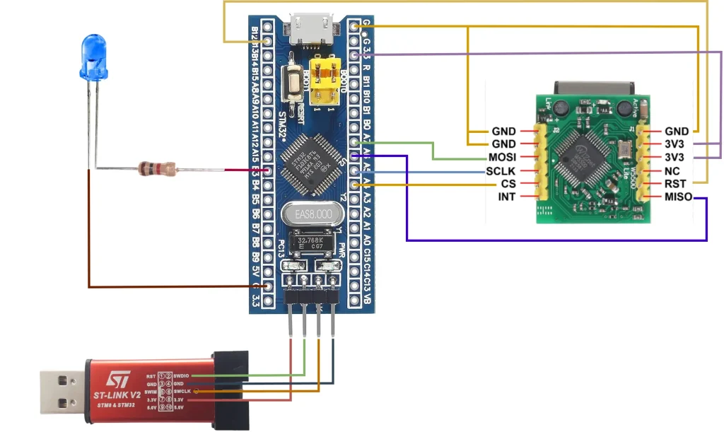
Please Note: Power both Stm32f103c8t6 and Wiznet W5500 Module from external 3.3V power supply. In this we used Stm32f103c8t6 internal power supply to power up the W5500 module which is not a good practice.
Pin Connections
| STM32F103C8T6 (Bluepill) | W5500 Module | ST Link V2 |
| PA6 | MISO | – |
| PA7 | MOSI | – |
| PA5 | SCLK | – |
| PA4 | CS | – |
| 3V3 (please use +3.3V external power Supply) | 3V3 (please use +3.3V external power Supply) | – |
| GND | GND | – |
| 3V3 (90 Degree Bent Pins) | 3V3 | |
| GND (90 Degree Bent Pins) | GND | |
| SWDIO (90 Degree Bent Pins) | SWDIO | |
| SCLK (90 Degree Bent Pins) | SCLK |
Then, connect the anode of an LED with a 1k resistor at PB3 and the other end to the ground.
Preparing STM32CubeIDE
To create a project in Stm32CubeIDE, please visit our previous tutorial. The link is given below:
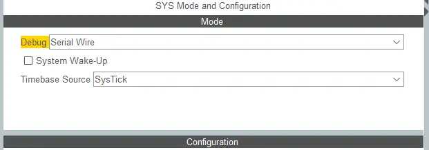
After creating the STM32CubeIDE project, from the CubeMX perspective, go to System core > sys, set ‘Serial Wire’ to Debug drop-down menu
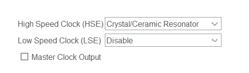
Also, go to System Core > RCC and set ‘Crystal/Ceramic Resonator’ to High Speed Clock (HSE)
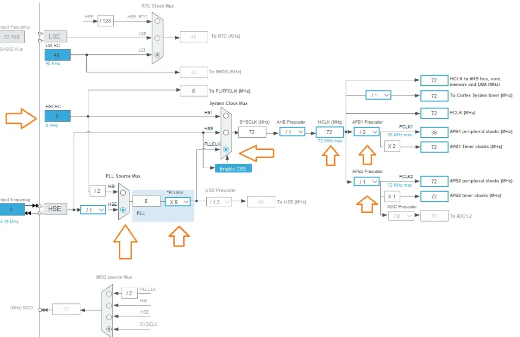
Then, open the Clock Configuration setting and select the clock source HSI of 8 MHz and generate a 72MHz clock using PLL of the STM32 microcontroller for the example project.
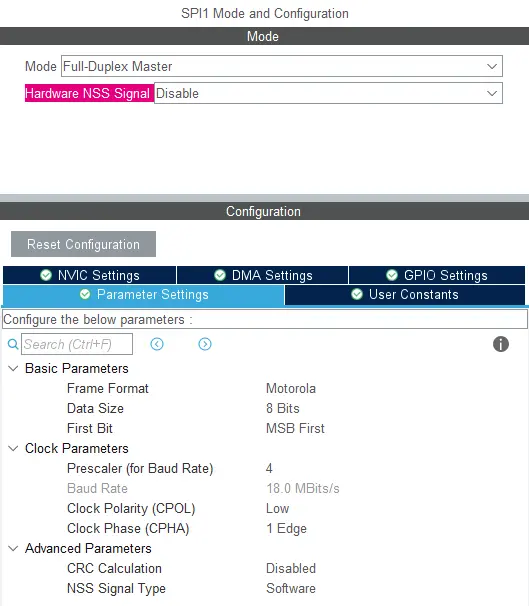
After that, click on the connectivity tab from the sidebar. Here we will use SPI1 for this project. Modify the SPI1 configuration according to the given screenshot below.
Then, in the pinout view, you will see some changes. You have to make some changes. Here, left-clicking at PA4, PB3, and PB13 sets it as GPIO OUTPUT. Again Right right-clicking the pins, change the user label according to the screenshots given below. Then, press the code generation button which looks like a little screw at the top left.
To make this project work, download the files from github links
- Wiznet Library
- Added Wiznet initialisation library
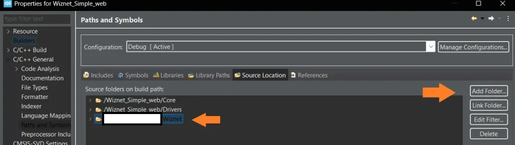
Add them to the project, and ensure that the source and include folder paths are included in the project. To do that, right click on the project name > properties > C/C++ general > Paths and Symbols. It should look like this:
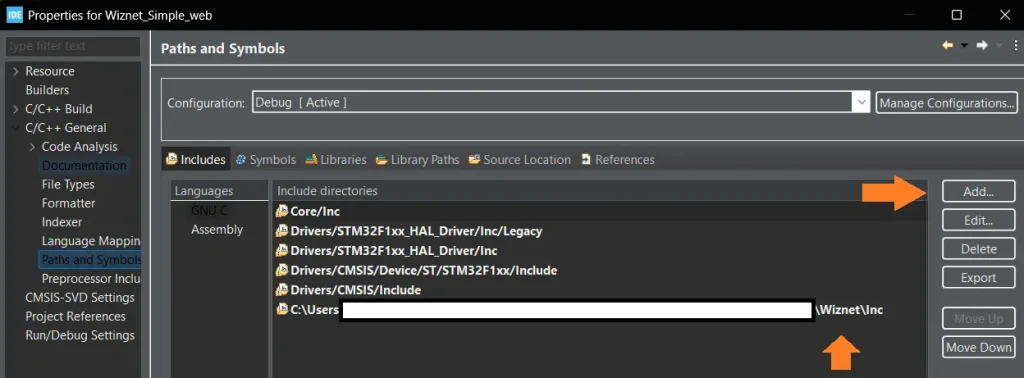
And
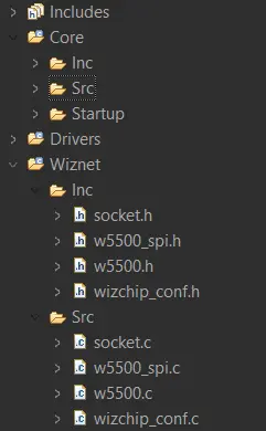
The sidebar of the project will look like this.
Code Explanation
| Code | Explanation |
| W5500Init(); | It initialised the Wiznet module. |
| wiz_NetInfo netInfo = { .mac = { 0x00, 0x08, 0xdc, 0xab, 0xcd, 0xef }, .ip = {192, 168, 0, 14 }, .sn = { 255, 255, 255, 0 }, .gw = { 192, 168, 0, 1 },.dns = { 8, 8, 8, 8 }, .dhcp = NETINFO_STATIC }; | Provide the IP address and corresponding gateway here. |
| #define SERVER_PORT 8080 | Give the server port |
 while (1)
  {
	  	if (socket(0, Sn_MR_TCP, SERVER_PORT, 0) == 0) {
	  	        if (listen(0) == SOCK_OK) {
	  	            while (1) {
	  	                if (getSn_SR(0) == SOCK_ESTABLISHED) {

	  	                	// Send Data to PC
	  	                    const char* message1 = "Hello World\r\n";
	  	                    send(0, (uint8_t*)message1, strlen(message1));
	  	                    HAL_Delay(100);

	  	                    // Checking whether Data received or not
	  	                    memset(recvBuffer, 0, sizeof(recvBuffer));
	  	                    if (getSn_RX_RSR(0) > 0) {
	  	                        recv(0, (uint8_t*)recvBuffer, getSn_RX_RSR(0));
	  	                    }
	  	                    // Receive Data from PC and confirm the received Data by sending another message to PC
	  	                    if (strncmp(recvBuffer, "Hello", 5) == 0) {
	  	                        const char* message2 = "Received\r\n";
	  	                        send(0, (uint8_t*)message2, strlen(message2));
	  	                        HAL_GPIO_TogglePin(LED_L1_GPIO_Port, LED_L1_Pin);
	  	                    }
	  	                }

	  	                if (!(getPHYCFGR() & PHYCFGR_LNK_ON)) {
	  	                    break;
	  	                }
	  	                if (getSn_SR(0) == SOCK_CLOSE_WAIT || getSn_SR(0) == SOCK_CLOSED) {
	  	                    disconnect(0);
	  	                    closesock(0);
	  	                    if (listen(0) != SOCK_OK) {
	  	                        break;
	  	                    }
	  	                }
	  	            }
	  	        }
	  	    }
This code sets up a TCP server using socket Channel 0 on a specified port. If the socket is successfully created, it starts listening for incoming connections. Inside an infinite loop, it checks whether a client has connected (SOCK_ESTABLISHED). If so, it sends a “Hello World” message to the client and waits briefly. It then clears the receive buffer and checks if any data has been received. If data is available, it reads it and checks if it starts with “Hello”.
If it does, it sends back a “Received” message and toggles an LED to indicate successful communication. The loop also monitors the physical network connection; if the Ethernet link is lost, it breaks out of the loop. Additionally, if the socket state changes to SOCK_CLOSE_WAIT or SOCK_CLOSED, it gracefully disconnects and closes the socket, then attempts to listen again. If listening fails, the loop breaks.
Full Code
main.c :
main.c :
/* USER CODE BEGIN Header */
/**
  ******************************************************************************
  * @file           : main.c
  * @brief          : Main program body
  ******************************************************************************
  * @attention
  *
  * Copyright (c) 2025 STMicroelectronics.
  * All rights reserved.
  *
  * This software is licensed under terms that can be found in the LICENSE file
  * in the root directory of this software component.
  * If no LICENSE file comes with this software, it is provided AS-IS.
  *
  ******************************************************************************
  */
/* USER CODE END Header */
/* Includes ------------------------------------------------------------------*/
#include "main.h"
/* Private includes ----------------------------------------------------------*/
/* USER CODE BEGIN Includes */
/* USER CODE END Includes */
/* Private typedef -----------------------------------------------------------*/
/* USER CODE BEGIN PTD */
/* USER CODE END PTD */
/* Private define ------------------------------------------------------------*/
/* USER CODE BEGIN PD */
/* USER CODE END PD */

/* Private macro -------------------------------------------------------------*/
/* USER CODE BEGIN PM */
/* USER CODE END PM */
/* Private variables ---------------------------------------------------------*/
SPI_HandleTypeDef hspi1;
/* USER CODE BEGIN PV */
char recvBuffer[128];// Data holder
wiz_NetInfo netInfo = { .mac = { 0x00, 0x08, 0xdc, 0xab, 0xcd, 0xef }, .ip = {
	  		192, 168, 0, 14 }, .sn = { 255, 255, 255, 0 }, .gw = { 192, 168, 0, 1 },
	  		.dns = { 8, 8, 8, 8 }, .dhcp = NETINFO_STATIC };
/* USER CODE END PV */
/* Private function prototypes -----------------------------------------------*/
void SystemClock_Config(void);
static void MX_GPIO_Init(void);
static void MX_SPI1_Init(void);
/* USER CODE BEGIN PFP */
/* USER CODE END PFP */
/* Private user code ---------------------------------------------------------*/
/* USER CODE BEGIN 0 */
/* USER CODE END 0 */
/**
  * @brief  The application entry point.
  * @retval int
  */
int main(void)
{
  /* USER CODE BEGIN 1 */
  /* USER CODE END 1 */
  /* MCU Configuration--------------------------------------------------------*/
  /* Reset of all peripherals, Initializes the Flash interface and the Systick. */
  HAL_Init();

  /* USER CODE BEGIN Init */
  /* USER CODE END Init */
  /* Configure the system clock */
  SystemClock_Config();
  /* USER CODE BEGIN SysInit */
  /* USER CODE END SysInit */
  /* Initialize all configured peripherals */
  MX_GPIO_Init();
  MX_SPI1_Init();
  /* USER CODE BEGIN 2 */
  W5500Init();
  /* USER CODE END 2 */
  /* Infinite loop */
  /* USER CODE BEGIN WHILE */
  while (1)
  {
	  	if (socket(0, Sn_MR_TCP, SERVER_PORT, 0) == 0) {
	  	        if (listen(0) == SOCK_OK) {
	  	            while (1) {
	  	                if (getSn_SR(0) == SOCK_ESTABLISHED) {

	  	                	// Send Data to PC
	  	                    const char* message1 = "Hello World\r\n";
	  	                    send(0, (uint8_t*)message1, strlen(message1));
	  	                    HAL_Delay(100);

	  	                    // Checking whether Data received or not
	  	                    memset(recvBuffer, 0, sizeof(recvBuffer));
	  	                    if (getSn_RX_RSR(0) > 0) {
	  	                        recv(0, (uint8_t*)recvBuffer, getSn_RX_RSR(0));
	  	                    }


	  	                    // Receive Data from PC and confirm the received Data by sending another message to PC
	  	                    if (strncmp(recvBuffer, "Hello", 5) == 0) {
	  	                        const char* message2 = "Received\r\n";
	  	                        send(0, (uint8_t*)message2, strlen(message2));
	  	                        HAL_GPIO_TogglePin(LED_L1_GPIO_Port, LED_L1_Pin);
	  	                    }
	  	                }

	  	                if (!(getPHYCFGR() & PHYCFGR_LNK_ON)) {
	  	                    break;
	  	                }

	  	                if (getSn_SR(0) == SOCK_CLOSE_WAIT || getSn_SR(0) == SOCK_CLOSED) {
	  	                    disconnect(0);
	  	                    closesock(0);
	  	                    if (listen(0) != SOCK_OK) {
	  	                        break;
	  	                    }
	  	                }
	  	            }
	  	        }
	  	    }
    /* USER CODE END WHILE */

    /* USER CODE BEGIN 3 */
  }
  /* USER CODE END 3 */
}
Please note: Certain portions of the code, specifically those automatically generated by STM32CubeIDE, have been omitted.
main.h :
/* USER CODE BEGIN Header */
/**
  ******************************************************************************
  * @file           : main.h
  * @brief          : Header for main.c file.
  *                   This file contains the common defines of the application.
  ******************************************************************************
  * @attention
  *
  * Copyright (c) 2025 STMicroelectronics.
  * All rights reserved.
  *
  * This software is licensed under terms that can be found in the LICENSE file
  * in the root directory of this software component.
  * If no LICENSE file comes with this software, it is provided AS-IS.
  *
  ******************************************************************************
  */
/* USER CODE END Header */
/* Define to prevent recursive inclusion -------------------------------------*/
#ifndef __MAIN_H
#define __MAIN_H
#ifdef __cplusplus
extern "C" {
#endif
/* Includes ------------------------------------------------------------------*/
#include "stm32f1xx_hal.h"
/* Private includes ----------------------------------------------------------*/
/* USER CODE BEGIN Includes */
#include "wizchip_conf.h"
#include "socket.h"
#include "w5500_spi.h"
#include <stdio.h>
#include <string.h>
/* USER CODE END Includes */
/* Exported types ------------------------------------------------------------*/
/* USER CODE BEGIN ET */
extern SPI_HandleTypeDef hspi1;
extern wiz_NetInfo netInfo;
/* USER CODE END ET */
/* Exported constants --------------------------------------------------------*/
/* USER CODE BEGIN EC */
/* USER CODE END EC */
/* Exported macro ------------------------------------------------------------*/
/* USER CODE BEGIN EM */
/* USER CODE END EM */

/* Exported functions prototypes ---------------------------------------------*/
void Error_Handler(void);
/* USER CODE BEGIN EFP */
/* USER CODE END EFP */
/* Private defines -----------------------------------------------------------*/
#define W5500_CS_Pin GPIO_PIN_4
#define W5500_CS_GPIO_Port GPIOA
#define W5500_RESET_Pin GPIO_PIN_13
#define W5500_RESET_GPIO_Port GPIOB
#define LED_L1_Pin GPIO_PIN_3
#define LED_L1_GPIO_Port GPIOB
/* USER CODE BEGIN Private defines */
#define SERVER_PORT 8080
/* USER CODE END Private defines */
#ifdef __cplusplus
}
#endif
#endif /* __MAIN_H */
W5500_spi.c :
#include "w5500_spi.h"
SPI_HandleTypeDef *spi_handle = &hspi1;
void mcu_cris_enter(void) {
	__set_PRIMASK(1);
}
void mcu_cris_exit(void) {
	__set_PRIMASK(0);
}
void wizchip_select(void) {
	  HAL_GPIO_WritePin(W5500_CS_GPIO_Port, W5500_CS_Pin, GPIO_PIN_RESET);
}

void wizchip_deselect(void) {
	  HAL_GPIO_WritePin(W5500_CS_GPIO_Port, W5500_CS_Pin, GPIO_PIN_SET);
}
uint8_t wizchip_read() {
	uint8_t rbuf;
	HAL_SPI_Receive(spi_handle, &rbuf, 1, 100);
	return rbuf;
}
void wizchip_write(uint8_t wb) {
	HAL_SPI_Transmit(spi_handle, &wb, 1, 100);
}
void wizchip_readburst(uint8_t* pBuf, uint16_t len) {
	for (uint16_t i=0; i<len; i++) {
		*pBuf = wizchip_read();
		pBuf++;
	}
}
void wizchip_writeburst(uint8_t* pBuf, uint16_t len) {
	for (uint16_t i=0; i<len; i++){
		wizchip_write(*pBuf);
		pBuf++;
	}
}

void W5500Init() {
	uint8_t tmp;
	// initialize the buffers, 2kb for each socket
	uint8_t memsize[2][8] = {{4,2,2,2, 2,2,1,1}, {4,2,2,2, 2,2,1,1}};
	// CS high by default, not selected by default
	HAL_GPIO_WritePin(W5500_CS_GPIO_Port, W5500_CS_Pin, GPIO_PIN_SET);
	// give the reset pin a brief pulse, to reset everything
	HAL_GPIO_WritePin(W5500_RESET_GPIO_Port, W5500_RESET_Pin, GPIO_PIN_RESET);
	tmp = 0xFF;
	while(tmp--);
	HAL_GPIO_WritePin(W5500_RESET_GPIO_Port, W5500_RESET_Pin, GPIO_PIN_SET);
	// point to the mcu specific functions
	reg_wizchip_cris_cbfunc(mcu_cris_enter, mcu_cris_exit);
	reg_wizchip_cs_cbfunc(wizchip_select, wizchip_deselect);
	reg_wizchip_spi_cbfunc(wizchip_read, wizchip_write);
	reg_wizchip_spiburst_cbfunc(wizchip_readburst, wizchip_writeburst);
	// wizchip initialize
	if (ctlwizchip(CW_INIT_WIZCHIP, (void*)memsize) == -1) {
		while(1);
		// @todo: handle this failed init case.
	}
	wizchip_setnetinfo(&netInfo);
	wizchip_getnetinfo(&netInfo);
}
W5500_spi.h :
#ifndef INC_W5500_SPI_H_
#define INC_W5500_SPI_H_
#include "main.h"
extern SPI_HandleTypeDef *spi_handle;
void W5500Init(void);
#endif /* INC_W5500_SPI_H_ */
Result
Serial Monitor view:
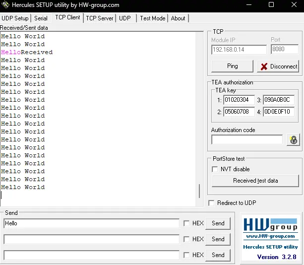
We will upload another article on the same topic, but using interrupts soon.