
In this article, we are going to provide a detailed explanation of the Raspberry Pi Pico and Pico W pinout. After that, you will be able to find the power pin, the PWM (Pulse Width Modulation) pin, the ADC (Analog to Digital Converter) pin, and the communication pin of the Raspberry Pi Pico and Pico W. This guide helps you make your projects easier.
Our other Raspberry Pi Pico related tutorials are:
- How to program Raspberry Pi Pico and Pico W using Arduino IDE
- How to interface Raspberry Pi Pico with RS485 Protocol
Introduction of Raspberry Pi Pico
The Raspberry Pi Pico is a high-performance microcontroller board with a low cost. It launched in early 2021, and after launching the original Raspberry Pico, several versions of the Pico came to market. The raspberry pi pico H, raspberry pi pico W, and raspberry pi pico WH are updated versions of the raspberry pi pico. Now move on to the features of the Raspberry Pi Pico.
Key features of Raspberry Pi Pico
- RP2040 microcontroller
- Dual-core Arm Cortex M0+ processor
- 133 MHz clock speed
- 264KB SRAM and 2MB flash memory
- Micro USB
- 2 × SPI, 2 × I2C, 2 × UART, 3 × 12-bit ADC, 16 × controllable PWM channels
- Built-in temperature sensor
Raspberry Pi Pico Vs Raspberry Pi Pico W
If you buy the Raspberry Pi Pico, you need to solder header pins to use the Raspberry Pi Pico, but the Pico H comes with pre-soldered headers. That is the only difference between Pico and Pico H. But there is a big difference between the Raspberry Pi Pico and the Pico W. The Raspberry Pi Pico W has single-band 2.4GHz wireless interfaces. Therefore, you can use WiFi and Bluetooth in your projects. And the Raspberry Pi Pico WH comes with pre-soldered headers.

Raspberry Pi Pico Purchase Links
| Component Name | Purchase Link |
|---|---|
| Raspberry Pi Pico | Amazon |
| Raspberry Pi Pico H | Amazon |
| Raspberry Pi Pico W | Amazon |
| Raspberry Pi Pico WH | Amazon |
Affiliate Disclosure: When you click on links to make a purchase, this can result in this website earning a commission. Affiliate programs and affiliations include, but are not limited to Amazon.com
Mapping of Raspberry Pi Pico Pins
The Raspberry Pi Pico and Pico W have a total of 40 pins. Among those 40 pins, 26 are programmable GPIOs, which means you can control your LED, motor, and sensors with those GPIOs. Other pins are power, ground, and run. We will discuss those pins individually later.
| Programmable GPIOs | Power | Ground(GND) | RUN | Total | |
|---|---|---|---|---|---|
| Number of Pins | 26 | 5 (One is ADC reference) | 8 | 1 | 40 |
You will find the pin labeling on the back of the Raspberry Pi Pico

Pinout Diagram of Raspberry Pi Pico

Pinout Diagram of Raspberry Pi Pico W

You will find the pinout diagram for the Raspberry Pi Pico on raspberrypi.com
Raspberry Pi Pico Peripherals
The RP2040 microcontroller is used in the Raspberry Pi Pico. Therefore, peripheral interfaces that are supported in the RP2040 are also supported in the Raspberry Pi Pico. The GPIOs of RP2040 microcontroller/ Raspberry Pi Pico run at 3.3v.
The Raspberry Pi Pico peripherals include:
- 4 ADC channels (12-bit)
- 16 PWM channels
- 2 SPI interfaces
- 2 I2C interfaces
- 2 UART interfaces
Powering Raspberry Pi Pico
The easiest way to power your pico is to connect pico with mico-USB. You can also power your pico by connecting VSYS and GND pin with 1.8V to 5.5v voltage source. The datasheet of the Pico is recommended to connect a Schottky diode with external power source(1.8V to 5.5V).
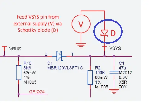
If the power source of Pico is micro-USB then you will get 5V on the VBUS pin.
Pico has a 3.3V fixed power pin that can help you to power the external circuit. It is recommended to keep the load on this pin less than 300mA.
Pico has four other power pins for special purpose. They are:
- 3V3_EN: To turn off the 3.3V power supply and shut down the RP2040, simply connect the 3V3_EN pin to the on-board SMPS enable pin, grounding it. This disables the 3.3V supply.
- ADC_VREF: The ADC_VREF pin on Pico serves as the power supply and reference voltage for the analog-to-digital converter (ADC). It is generated within the Pico by filtering the 3.3V supply. If you need improved ADC performance, you can use this pin as an external reference voltage.
- AGND: Ground pin for ADC.
- RUN: You can reset your Pico to set this pin Low.
General Purpose Input/Output(GPIO) Pins
The Pico provides access to 26 out of the 30 available RP2040 (microcontroller) GPIO pins through direct connections to Pico header pins. GPIO pins 0 to 22 are exclusively for digital purposes, while GPIO pins 26 to 28 can function as either digital GPIO or as analog-to-digital converter (ADC) inputs, and you can switch between these modes through software settings.
Rest of four GPIOs of RP2040 are fixed for internal functionality. Thery are:
- GPIO23: Output pin. Controls the RT6150 PS (Power Save) pin
- GPIO24: Input pin. Indicator of VBUS presence. High, if VBUS is present otherwise low.
- GPIO25: Output pin: Output pin. Fixed for on board LED
- GPIO29: Input pin: Used for measuring VSYS in ADC mode.
Note: GPIO23,24,25, and,29 pins are not visible on the Pico board. They are used internally for internal functionality.
Analog to Digital Converter (ADC) Pins
The Raspberry Pi Pico has three analog pins to read analog values from sensors. Although two other pins also support analog reading, they are not labeled on the Pico board. One is used for measuring VSYS voltage, and the other is used for controlling the built-in temperature sensor.
| GPIO | ADC channel | Function |
|---|---|---|
| GPIO26 | ADC0 | Used to read analog values from peripherals (12-bit resolution) |
| GPIO27 | ADC1 | Used to read analog values from peripherals (12-bit resolution) |
| GPIO28 | ADC2 | Used to read analog values from peripherals (12-bit resolution) |
| GPIO29 | ADC3 | Used to measure VSYS voltage level (12-bit resolution) |
| – | ADC4 | Used to control built-in temperature sensor |
A short note of Pico ADC
- 12-bit resolution. That means it can slice an analog signal to 0 to samples.
- Three accessible ADC channels (ADC0, ADC2, ADC2 or GPIO26, GPIO27, GPIO28) for peripherals
- On board ADC reference voltage (3.3V) with filtering and ADC ground (AGND). So, you need not any eternal ADC reference voltage in your project.
Pulse Width Modulation (PWM) Pins
The Raspberry Pi Pico has 8 pairs of Pulse Width Modulation (PWM) channels. Each pair has two channels A and B.

Note:
- The same PWM output can be selected on two GPIO pins; the same signal will appear on each GPIO. For example, you can get same output on GPIO0 and GPIO16.
- Pico PWM is 16-bit that means the range of period is 0 to 65536 cycles.
Inter-Integrated Circuit (I2C) pins
The Pico has two identical I2Cs. one is I2C0 and other one is I2C1. I2C needs two pins, SDA and SCL. The SDA and SCL pins of two I2Cs are shown below.

Serial Peripheral Interface (SPI) Pins
The Pico has two identical SPI. one is SPI0 and other one is SPI1. SPI needs four pins, Rx, Tx, CLk (clock), and CS. The Rx, Tx, CLk (clock) and CS pins of two SPIs are shown below.
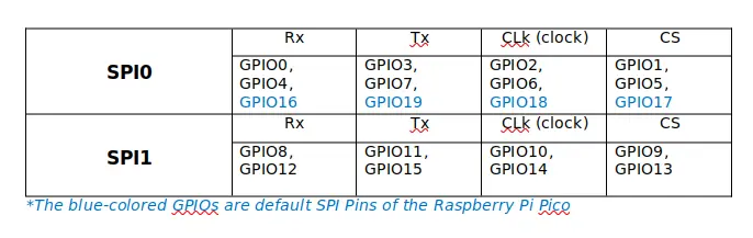
Note: You cannot use two of the same SPI at the same time. Therefore, if you need two SPIs, you can use one from SPI0 and the other from SPI1.
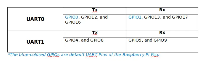
Universal Asynchronous Receiver / Transmitter (UART) Pins
The Raspberry Pi Pico has a total of five pairs of pins for UART communication. Three pairs are associated with UART0, and the other two are for UART1. The responsible GPIOs are shown below table.
Debugging Pins
you will find the three debug pins bottom of the board and the labeling back on the Pico. In Pico w they are maybe middle on the board. The three debugging pins are WDIO (Serial Wire Debug I/O), GND, and SWCLK (Serial Wire Clock).
GND: This pin serves as the grounding connection for the two-wire interface.
SWCLK (Serial Wire Clock): Associated with the SWD interface, this pin supplies the clock signal crucial for synchronized communication during debugging.
SWDIO (Serial Wire Debug I/O): This bidirectional pin is a key component of the SWD interface, handling both control and data signals during debugging.
These pins grant direct access to vital signals and interfaces on the Pico board. They enable you to observe and analyze the system’s behavior throughout the debugging process, which can be simplified using a Raspberry Pi Debug Probe.