
RS485 is one of the most popular communication protocols in the industry because of its long-distance capability and noise immunity. In this tutorial, I will show you how you can communicate between your Raspberry Pi Pico and Arduino using the RS485 protocol in your project.
Introduction
If you want to communicate between Raspberry Pi Pico with other microcontrollers such as Arduino in a long range of about 20-30 meters then RS485 communication will be the best option. In this tutorial, I will demonstrate complete interfacing between Pico and Arduino Nano using the MAX485 TTL module. Also, you will able to control a GPIO pin using RS485 communication.
Recommended Tutorials:
- RS485 Communication Protocol: Basics, Working Principle & Applications
- How to interface Arduino with RS485 (Modbus) protocol
- How to interface Modbus RTU (RS485) sensors with Arduino
- Multiple ESP32 Communication via RS485
- How to interface ESP32 with RS485 (Modbus) sensors with example code
Our other Raspberry Pi Pico related tutorials are:
- A Complete Pinout Guide of Raspberry Pi Pico and Pico W
- How to program Raspberry Pi Pico and Pico W using Arduino IDE
- Raspberry Pi Pico ADC tutorial using Arduino IDE
What is MAX485 TTL Module?
MAX485 module converts TTL logic levels to RS-485 voltage levels, supports half-duplex communication, and is commonly used in industrial automation and other applications where reliable long-distance communication is needed.

MAX485 Pin description:
RO: Receiver Output
RE: Receiver Enable, Active LOW when receiving data
DE: Driver Enable, Active HIGH when transmitting data
DI: Driver Input
A: Non-inverting Driver Output and Receiver Input
B: Inverting Driver Output and Receiver Input
VCC: 4.75 Volt to 5.25 Volt
Features of MAX485
- Low power
- Half-duplex (Transmitter and Receiver don’t receive or send data at the same time)
- Up to 5Mbps data rate
- Long distance communication
Raspberry Pi Pico UART Communication
Before moving into the project you have to know about Pico UART because the MAX485 is commonly used to convert UART (Universal Asynchronous Receiver/Transmitter) signals to RS-485 signals. Raspberry Pi Pico has two, UART0 and UART1. The pin mapping of UART0 and UART1 is shown below.

You can only configure one pair of pins from UART0 or UART1 that means, if you want to use UART1 then you configure GPIO8 as Tx and GPIO9 as Rx then you cannot use GPIO4 and GPIO5 as UART in the same program. So, if you need you can use both UART(UART0 and UART1).
Recommended Article: A Complete Pinout Guide of Raspberry Pi Pico and Pico W: GPIOs Explanation
Preparing Arduino IDE for the project
Installing Arduino Mbed OS RP2040 Board
To avoid errors in your code I recommended installing the Arduino Mbed OS RP2040 board in your Arduino IDE.
Recommended Article: How to program Raspberry Pi Pico and Pico W using Arduino IDE
Step 01: Go to Tools>>Board>>Board Manager
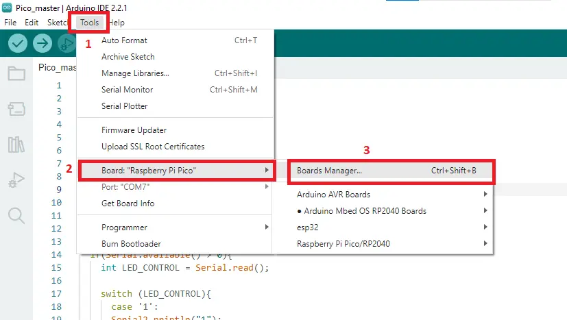
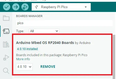
Step 02: Search for Pico then install Arduino Mbed OS RP2040 Boards
Step 03: Restart your Arduino IDE.
Communication between Raspberry Pi Pico and Arduino Nano Using RS485: The Project
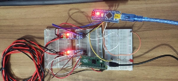
Now, with an example, I will show you how you can send and receive data using RS485 and control a LED. You can use this idea in your project.
Component List
| Component Name | Quantity | Links |
|---|---|---|
| Raspberry Pi Pico or Raspberry Pi Pico W | 1 | Amazon.com | Amazon.com | AliExpress |
| Arduino Nano | 1 | Amazon.com | AliExpress |
| MAX485 TTL Module | 2 | Amazon.com | AliExpress |
| LED | 1 | Amazon.com | AliExpress |
| 330 ohms resistor | 1 | Amazon.com | AliExpress |
| Breadboard | 1 | Amazon.com | AliExpress |
| Jumper Wire Pack | 1 | Amazon.com | AliExpress |
Circuit Diagram of the Project
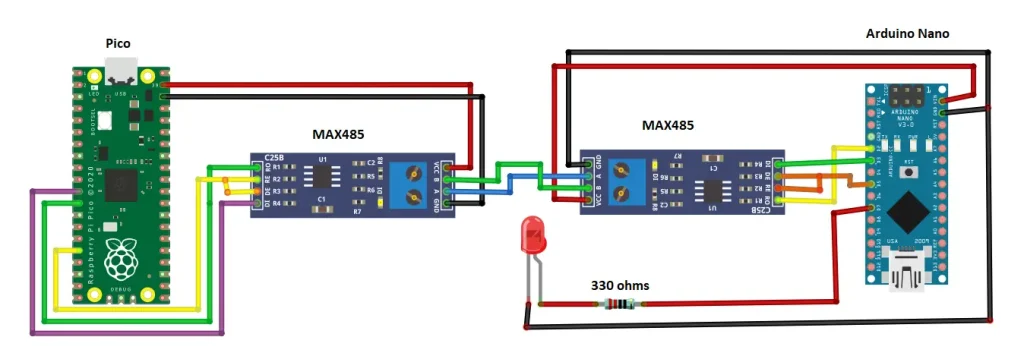
Connection between Raspberry Pi Pico and MAX485
| Raspberry Pi Pico | MAX485 |
|---|---|
| VSYS | VCC |
| GND | GND |
| GPIO 8 (TX) | DI |
| GPIO 9 (RX) | RO |
| GPIO 12 | DE, and RE |
Connection between Arduino Nano and MAX485
| Arduino Nano | MAX485 |
|---|---|
| VIN | VCC |
| GND | GND |
| D2 (RX) | RO |
| D3 (TX) | DI |
| D5 | DE, and RE |
Code Description
Master code description
At master, to send a command to slave I use Serial2 so that I configure GPIO8 as Tx and GPIO9 as Rx of Raspberry Pi Pico respectively. The rest of the values are not important that’s why I make these 0 and 0.
UART Serial2(8, 9, 0, 0);
After that, I define the RS485 control pin as GPIO 12 of Raspberry Pi Pico.
#define rs485_control_pin 12
In the setup function, define two baud rates 9600 of Serial and Serial2. Set the RS485(which controls the DE and RE of MAX485) control pin as output and make it HIGH because to transmit data DE and RE pins must be HIGH. And for receiving data this pin must be LOW.
void setup() {
  Serial.begin(9600);
  Serial2.begin(9600);
  pinMode(rs485_control_pin,OUTPUT);
  digitalWrite(rs485_control_pin,HIGH);
}
In the loop function to transmit data set the RS485 control pin HIGH. Now, we send data to the slave through the MAX485 A B lines. If we send ‘1’ to the slave then the LED will turn ON and if we send ‘0’ the slave LED will turn OFF. This command will be written in the serial monitor of the Arduino IDE and the command will rend using Serial.read(); function.
digitalWrite(rs485_control_pin,HIGH);
  if(Serial.available() > 0){
    int LED_CONTROL = Serial.read();

    switch (LED_CONTROL){
      case '1':
      Serial2.println("1");
      Serial.print("LED ON");
      delay(100);
      break;

      case '0':
      Serial2.println("0");
      Serial.print("LED OFF");
      delay(100);
      break;

      default:
      Serial.println(" ");
      break;
  }
  }
Now, to read data from the slave set the RS485 control pin to LOW. When Serial2 is available the Serial2.readString() reads the data from Serial2 and prints it to the Arduino serial monitor.
digitalWrite(rs485_control_pin,LOW);
  if(Serial2.available()>0){
    Serial.println(Serial2.readString());
  }
Master Full Code
#include <Arduino.h>
UART Serial2(8, 9, 0, 0);  //tx rx
#define rs485_control_pin 12
void setup() {
  Serial.begin(9600);
  Serial2.begin(9600);
  pinMode(rs485_control_pin,OUTPUT);
  digitalWrite(rs485_control_pin,HIGH);
}

void loop() {
  digitalWrite(rs485_control_pin,HIGH);
  if(Serial.available() > 0){
    int LED_CONTROL = Serial.read();

    switch (LED_CONTROL){
      case '1':
      Serial2.println("1");
      Serial.print("LED ON");
      delay(100);
      break;

      case '0':
      Serial2.println("0");
      Serial.print("LED OFF");
      delay(100);
      break;

      default:
      Serial.println(" ");
      break;
  }
  }
  digitalWrite(rs485_control_pin,LOW);
  if(Serial2.available()>0){
    Serial.println(Serial2.readString());
  }
  delay(100);
}
Slave Code description
we are using Arduino Nano as a slave in our project. At first include the software serial library function because we are not going to use the default serial of the nano. Define GPIO2 and GPIO3 as Rx and Tx respectively. Define GPIO5 as RS485 control pin and GPIO5 as LED pin.
#include <SoftwareSerial.h>
const byte Rx_pin = PD2;
const byte Tx_pin = PD3;
// Set up a new SoftwareSerial object
SoftwareSerial mySerial (Rx_pin, Tx_pin);
#define rs485_control_pin PD5
#define LED PD7
In setup function set the baud rate 9600 of serial and myserial. Set the RS485 control pin and LED pin as output.
void setup() {
  Serial.begin(9600);
  mySerial.begin(9600);
  pinMode(rs485_control_pin,OUTPUT);
  digitalWrite(rs485_control_pin,LOW);
  pinMode(LED,OUTPUT);
  digitalWrite(LED,LOW);
}
In the loop function to receive data set the RS485 control pin is LOW. When data is coming from the master which is detected by mySerial.available(). When the slave receives ‘1’ the LED will turn ON for two seconds and when the slave receives ‘0’ the LED will turn OFF. To send data to the master set the RS485 control pin HIGH and send data using an Arduino serial monitor.
digitalWrite(rs485_control_pin,LOW);
  if(mySerial.available() > 0){
    int Recv_Data = mySerial.parseInt();
    if (Recv_Data == 1) {
      digitalWrite(LED, HIGH);         //LED On
      delay(2000);
    }
    else if (Recv_Data == 0) {
      digitalWrite(LED, LOW);       //LED Off
    }
  }
  if(Serial.available() > 0){
    digitalWrite(rs485_control_pin,HIGH);
    mySerial.println(Serial.readString());
  }
Slave Full code
#include <SoftwareSerial.h>
const byte Rx_pin = PD2;
const byte Tx_pin = PD3;
// Set up a new SoftwareSerial object
SoftwareSerial mySerial (Rx_pin, Tx_pin);
#define rs485_control_pin PD5
#define LED PD7

void setup() {
  Serial.begin(9600);
  mySerial.begin(9600);
  pinMode(rs485_control_pin,OUTPUT);
  digitalWrite(rs485_control_pin,LOW);
  pinMode(LED,OUTPUT);
  digitalWrite(LED,LOW);

}

void loop() {
  digitalWrite(rs485_control_pin,LOW);
  if(mySerial.available() > 0){
    int Recv_Data = mySerial.parseInt();
    if (Recv_Data == 1) {
      digitalWrite(LED, HIGH);         //LED On
      delay(2000);
    }
    else if (Recv_Data == 0) {
      digitalWrite(LED, LOW);       //LED Off
    }
  }

  if(Serial.available() > 0){
    digitalWrite(rs485_control_pin,HIGH);
    mySerial.println(Serial.readString());

  }
  delay(100);
}
Uploading the Code
Master
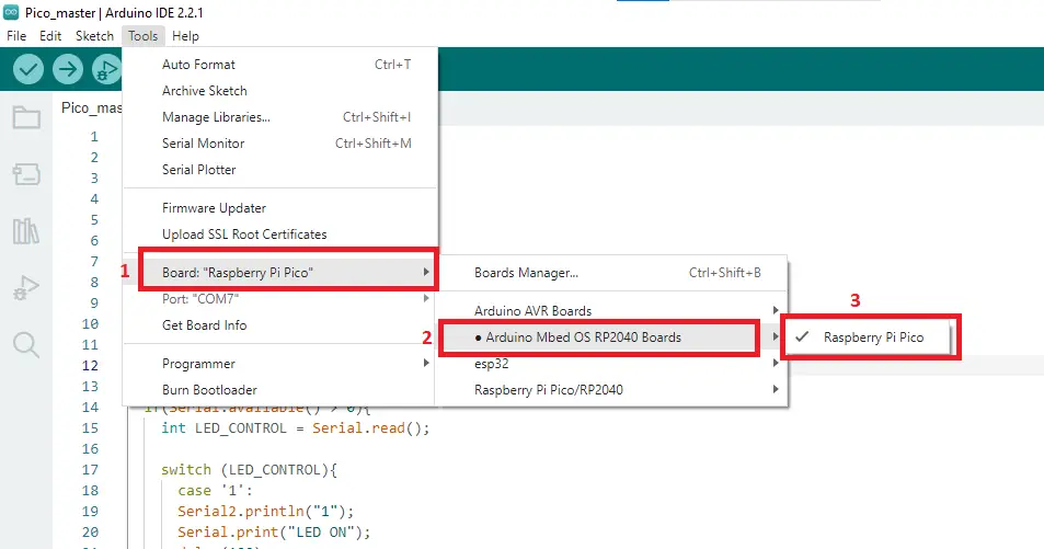
Step01: Now, go to Tools>>Board>>Arduino Mbed OS RP2040 boards>>Raspberry Pi Pico.
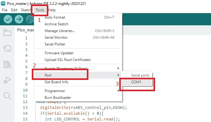
Step02:Connect your Pico with your PC and select the right port where your Pico is connected. Go to tools>>Port>>select the port (In my case it was COM1).
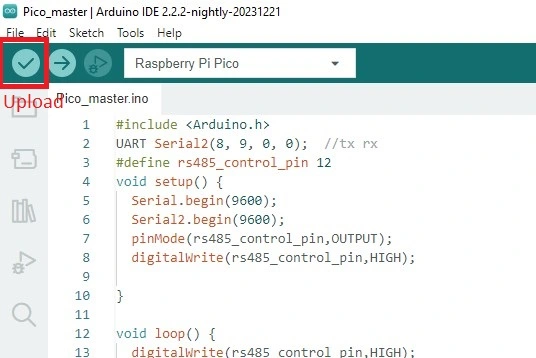
Step 03: Hit the upload button to compile and upload your code
Slave
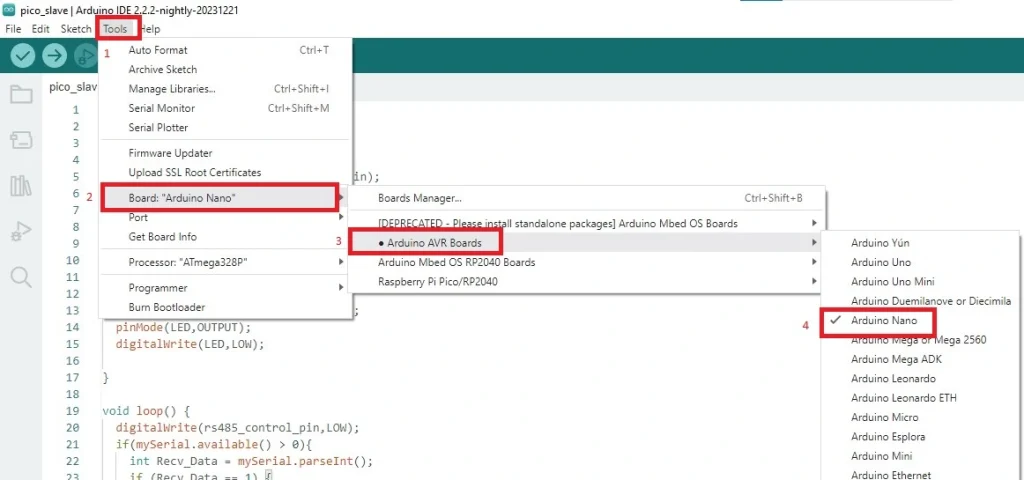
Step01:Now, go to Tools>>Board>>Arduino AVR boards>>Arduino Nano
Rest of two steps same as master.
Conclusion
Using RS485 communication, you can communicate between your Raspberry Pi Pico and Arduino at a long distance in your project. Also, you can configure up to 32 slaves using RS485 communication.