In this tutorial, we will discuss how to interface Arduino (as master) to any Modbus RTU (RS485) based sensor (as a slave) using Arduino IDE. We will create an example project by interfacing an RS485 Modbus protocol-based energy meter (DDM18SD) using MAX485 (TTL to RS485) module and collect current, voltage, and frequency data from it.
Get 50% Off My Embedded Systems Book
Watch a short ad to unlock the special discount link for my book.
You may also like reading:
- RS485 Communication Protocol: Basics, Working Principle & Application
- Introduction to RS232 Serial Communication Protocol
- How to interface esp32 with rs485 (Modbus) sensors with example code
- Multiple ESP32 Communication via RS485
- How to interface Arduino with RS485 (Modbus) protocol
Our other Arduino-related tutorials are:
- Arduino Lora tutorial with Example code
- Interfacing Arduino with Bluetooth Module (HC-05) : Example Code Included
Introduction
Modbus RTU (RS485) is a popular communication protocol used in industrial automation applications for communication between devices. The protocol is widely used because it is robust and easy to implement. In this tutorial, we will explore how to interface an Arduino as a master with a Modbus RTU (RS485) sensor as a slave device. To interface an Arduino with a Modbus RTU (RS485) sensor, we will use an RS485 to TTL module (MAX485) to convert the RS485 signal to TTL signal that can be understood by the Arduino. We also need to write an Arduino code using the Modbus master library to communicate with the Modbus RTU (RS485) sensor. Finally, we will build a real-world project that will read voltage, current, and power factor values from a Modbus RTU (RS485) enabled Energy meter (DDM18SD) and print it to the serial monitor of Arduino IDE.
What Modbus RTU is and how it works
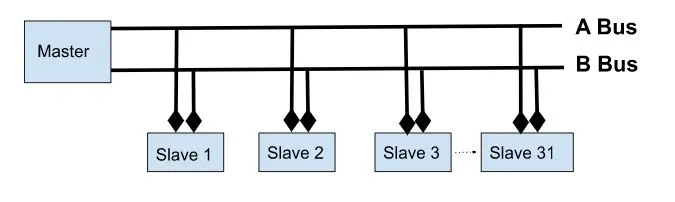
Modbus RTU is a serial communication protocol that was developed by Modicon in 1979. The protocol is based on the master-slave architecture, where the master initiates the communication and the slave responds to the master’s requests. In the Modbus RTU protocol, data is transmitted in a binary format over a serial communication link using the RS485 interface.
If you want to read more about RS485 and Modbus protocol, please visit the link below:
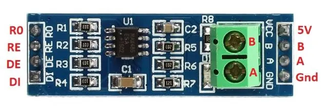
MAX485 – RS485 to TTL Converter
The MAX485 is a popular RS485 to TTL converter chip that is used in many industrial automation and communication applications. The MAX485 chip is designed to convert the RS485 signal to TTL signal that can be understood by microcontrollers like Arduino. The chip has a low-power shutdown mode and can operate at a maximum data rate of 2.5Mbps. The MAX485 chip is widely used because it is easy to use and can handle long communication distances of up to 4000 feet. The chip is also affordable and readily available in the market, making it a popular choice for many electronics hobbyists and professionals alike.
Features of the MAX485
- Low power consumption: The MAX485 chip has a low power shutdown mode which can help to conserve power in applications where power consumption is critical.
- Long communication distance: The MAX485 chip can handle long communication distances of up to 4000 feet, which makes it ideal for use in industrial automation and communication applications.
- High data rate: The chip can operate at a maximum data rate of 2.5Mbps, which makes it suitable for applications that require high-speed communication.
- Low cost: The chip is affordable and readily available in the market, making it a popular choice for many electronics hobbyists and professionals.
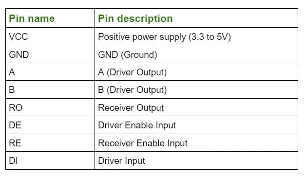
MAX485 Pin Description
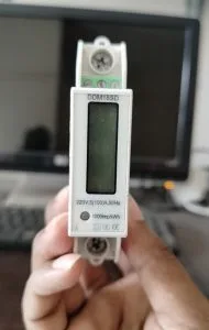
DDM18SD Energy meter
The DDM18SD Energy meter is a Modbus RTU (RS485) enabled energy meter used to measure and monitor electrical energy consumption in industrial and commercial settings. It has a compact design with a backlit LCD display that shows real-time energy consumption data in kilowatt-hours (kWh). The energy meter is easy to install and supports both single-phase and three-phase systems. It also has a built-in RS485 communication port that allows for easy integration with industrial automation systems. The DDM18SD energy meter is widely used in power distribution and management systems in industries such as manufacturing, data centers, and commercial buildings.
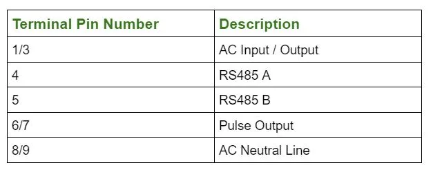
DDM18SD Pin Description
Interfacing Arduino with DDM18SD using Modbus RTU protocol (The project)
In this section of the tutorial, we will first draw the circuit diagram of the rs485 communication between Arduino (as master) and DDM18SD (as a slave sensor). After that, we will code an example project which is to collect the voltage (in Volt), current (in Amps), and frequency (in Hz) data from DDM18SD energy meter vai MAX485 IC to Arduino. Then we will show the collected data to Arduino IDE serial monitor.
Component List
[wptb id=924]
For troubleshooting, some extremely useful test equipment
[wptb id=890]
Affiliate Disclosure: When you click on links to make a purchase, this can result in this website earning a commission. Affiliate programs and affiliations include, but are not limited to Amazon.com
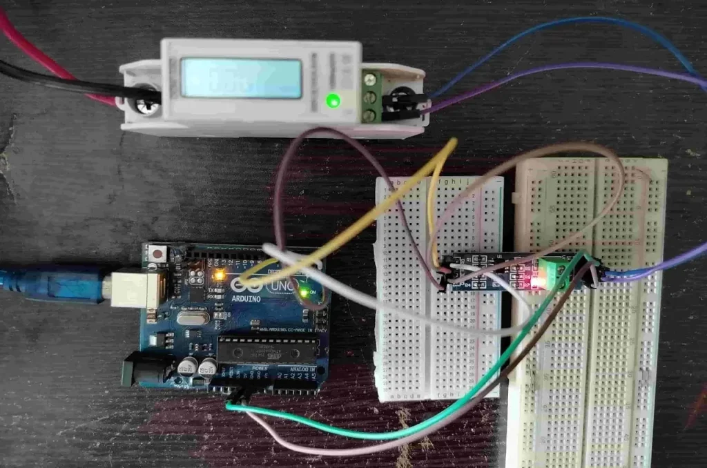
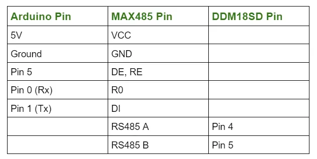
Circuit Connection between Arduino Uno, MAX485 and DDM18SD
Preparing Arduino IDE
Step 1: Just open your Arduino IDE and go to File > New and open a new file.
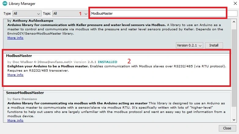
Step 2: Then go to Tools > manage Libraries and search for ModbusMaster by Doc walker in the search bar the hit Install.
Important Modbus Library Functions
The following Modbus functions are available in this library:
Discrete Coils/Flags functions:
- 0x01 – Read Coils
readCoils(uint16_t u16ReadAddress, uint16_t u16BitQty);
- 0x02 – Read Discrete Inputs
readDiscreteInputs(uint16_t u16ReadAddress, uint16_t u16BitQty);
- 0x05 – Write Single Coil
writeSingleCoil(uint16_t u16WriteAddress, uint8_t u8State);
- 0x0F – Write Multiple Coils
writeMultipleCoils(uint16_t u16WriteAddress, uint16_t u16BitQty);
Registers functions:
- 0x03 – Read Holding Registers
readHoldingRegisters(uint16_t u16ReadAddress, uint16_t u16ReadQty);
- 0x04 – Read Input Registers
readInputRegisters(uint16_t u16ReadAddress, uint8_t u16ReadQty);
- 0x06 – Write Single Register
writeSingleRegister(uint16_t u16WriteAddress, uint16_t u16WriteValue);
- 0x10 – Write Multiple Registers
writeMultipleRegisters(uint16_t u16WriteAddress, uint16_t u16WriteQty);
- 0x16 – Mask Write Register
maskWriteRegister(uint16_t u16WriteAddress, uint16_t u16AndMask, uint16_t u16OrMask);
- 0x17 – Read Write Multiple Registers
readWriteMultipleRegisters(uint16_t u16ReadAddress, uint16_t u16ReadQty, uint16_t u16WriteAddress, uint16_t u16WriteQty);
Please Note: All these functions return 0 on success; exception number on failure. If you want to read more about the library, please visit its GitHub page.
Full Code
// github link: https://github.com/4-20ma/ModbusMaster
#include <ModbusMaster.h>
/* Modbus stuff */
#define MODBUS_DIR_PIN 5 // connect DR, RE pin of MAX485
#define MODBUS_RX_PIN 0 // Rx pin
#define MODBUS_TX_PIN 1 // Tx pin
#define MODBUS_SERIAL_BAUD 9600 // Baud rate for modbus rtu communication
// voltage, current and frequency register of Energy Meter
// if you want to read more parameters, then increase the array size
//and, write the address
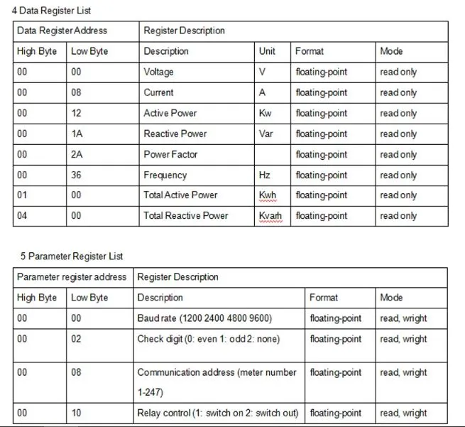
uint16_t data_register[3] = {0x0000, 0x0008, 0x0036};
//Initialize the ModbusMaster object as node
ModbusMaster node;
// Pin 4 made high for Modbus transmision mode
void modbusPreTransmission()
{
delay(500);
digitalWrite(MODBUS_DIR_PIN, HIGH);
}
// Pin 4 made low for Modbus receive mode
void modbusPostTransmission()
{
digitalWrite(MODBUS_DIR_PIN, LOW);
delay(500);
}
void setup() {
//we initialize the built-in hardware serial communication
//using the Serial.begin() function with two parameters.
//The first parameter is the desired baud rate (9600 bits per second),
//and the second parameter is SERIAL_8E1,
//which specifies the data format (8 data bits, even parity, and 1 stop bit).
//to set these two parameter, please read your sensor datasheet first
Serial.begin(9600, SERIAL_8E1);
while (!Serial) {
; // wait for serial port to connect. Needed for native USB port only
}
pinMode(MODBUS_DIR_PIN, OUTPUT);
digitalWrite(MODBUS_DIR_PIN, LOW);
//modbus device slave ID 14
node.begin(14, Serial);
// callbacks allow us to configure the RS485 transceiver correctly
node.preTransmission(modbusPreTransmission);
node.postTransmission(modbusPostTransmission);
}
void loop()
{
uint8_t result;
//for store 32-bit data
uint16_t data[2];
int i;
float reading;
// this loop is to read voltage, current and power factor register of Energy Meter
for(i=0; i<=2; i++){
//Modbus function code (0x04) Read Input Registers according to energy meter datasheet
result = node.readInputRegisters(data_register[i], 1);
if (result == node.ku8MBSuccess) {
Serial.println("Success, Received data: ");
//Retrieve the data from getResponseBuffer(uint8_t u8Index) function.
//that is return 16-bit data. our energy meter return 32-bit data everytime.
//that's why, we take the value to a array called data
data[0]=node.getResponseBuffer(0x00);
data[1]=node.getResponseBuffer(0x01);
//read voltage
if(data_register[i] == 0x0000){
Serial.print("Volatge: ");
reading = *((float *)data);
Serial.print(reading);
Serial.println(" Volt");
}
//read current
if(data_register[i] == 0x0008){
Serial.print("Current: ");
reading = *((float *)data);
Serial.print(reading);
Serial.println(" Amps");
}
//read Frequency
if(data_register[i] == 0x0036){
Serial.print("Frequency: ");
reading = *((float *)data);
Serial.print(reading);
Serial.println(" Hz");
}
} else {
Serial.print("Failed, Response Code: ");
Serial.print(result, HEX);
Serial.println("");
delay(5000);
}
}
//one second delay
delay(1000);
}
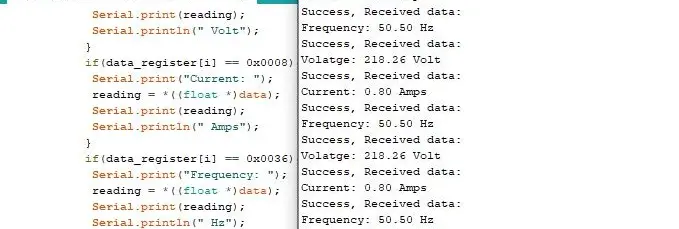
Output of the Code
The output of the code in Arduino IDE serial monitor
DDM18SD energy meter RS485 (Modbus RTU) register reference