
In this tutorial, we will explain how to communicate between two Arduino boards with the help of the RS485 serial data communication protocol. Arduino doesn’t have any peripherals for RS485 communication. We will use an RS485-based sensor module called MAX485 for communication between two Arduino boards. We will follow the RS485 master-slave communication method. For demonstration purposes, we will create a project that will ON or OFF a LED connected to a Slave Arduino from Master Arduino by sending some commands through RS485 Module.
You may also like reading:
- How to interface Modbus RTU (RS485) sensor with Arduino
- How to interface STM32 with RS485 (Modbus) sensors
- Introduction to RS232 Serial Communication Protocol
- How to interface Arduino with RS232 communication protocol
- How to interface esp32 with rs485 (Modbus) sensors with example code
- Multiple ESP32 Communication via RS485
What is RS485?
There are different types of physical media and they are:
- RS232: serial communication protocol
- RS485: serial communication protocol
- RS422: serial communication protocol
- Ethernet: LAN (Local Area Network) Technology
RS485 is an asynchronous half-duplex serial communication protocol that communicates over devices by using the master-salve method. It can connect a maximum of 32 devices on the same line.
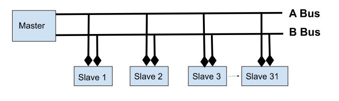
Most of the industry uses RS485 protocol rather than RS232 because of its longer distances (up to 1200 meters), higher data transfer rate (Up to 30Mbps), and allow for multiple devices connection on a single network by using only two wires.
MAX485 TTL to RS485 Module
MAX485 is a low-power transceiver for TTL to RS485 communication. This module needs 5V to operate and uses a 5V logic level so that it can be easily interfaced with microcontrollers like Arduino.
Key Features of MAX485:
- It can cover longer distances of up to 1200 meters
- Supports a higher data transfer rate of 10Mbit/s
- MAX485 can connect a maximum of 32 devices
- A low power consumption
- Slew-rate limited transceiver
- Onboard 5.08mm pitch 2P terminal for RS-485 communication wiring
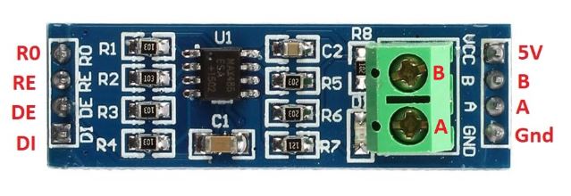
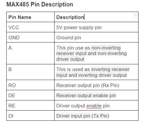
MAX485 Module Pinout
RS485 communication between two Arduino boards by using MAX485 module (The project)
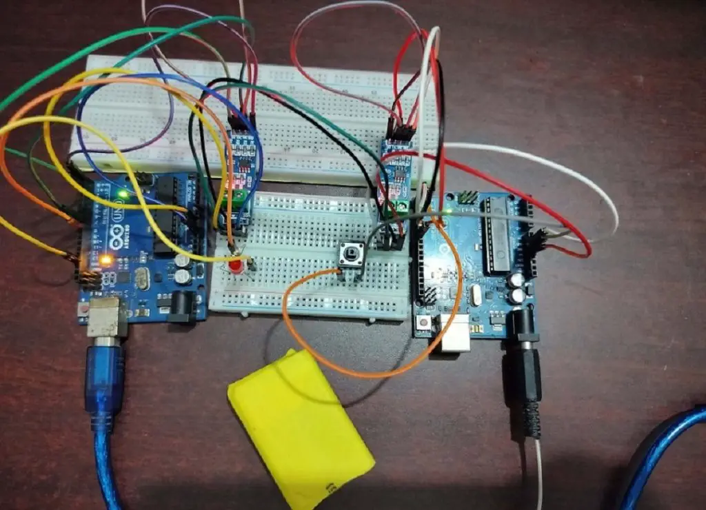
In this part of the article, We will explain how the RS485 communication works by doing of a simple project. We will use two Arduino Uno boards for this project. One is used as a master and another is as a slave. We will send a command “1” or “0” from the master to the slave. Slave will receive and check the value. If the value is “1” then the slave turns on a LED and prints “LED ON” on the serial monitor of Arduino IDE or if the value is “0” the slave turns off the led and prints “LED OFF” in the serial monitor of Arduino IDE.
We use a 5V Li-ion battery to power the master Arduino Board and for power the slave Arduino we use a computer 5V USB power supply.
Component List
To follow the project you will need several components and they are:
| Component Name | Quantity | Purchase Link |
|---|---|---|
| Arduino development board | 2 | Amazon | AliExpress |
| Push button | 1 | Amazon | AliExpress |
| MAX485 TTL to RS485 converter module | 2 | Amazon | AliExpress |
| Breadboard | 1 | Amazon | AliExpress |
| Jumper Wire pack | 1 | Amazon | AliExpress |
| LED | 1 | Amazon | AliExpress |
| 100 ohm Resistor | 1 | Amazon | AliExpress |
For troubleshooting, some extremely useful test equipment
| Equipment Name | Purchase Link |
|---|---|
| Best Oscilloscope for Professionals | Amazon | AliExpress |
| Best Oscilloscope for Beginners | Amazon | AliExpress |
| Logic Analyzer | Amazon | AliExpress |
| Best Budget Multimeter | Amazon | AliExpress |
Affiliate Disclosure: When you click on links to make a purchase, this can result in this website earning a commission. Affiliate programs and affiliations include, but are not limited to Amazon.com
Circuit Schematics
In this article section, We will show you how to connect MAX485 module to Arduino Uno with the help of the connection diagram and pin description table.
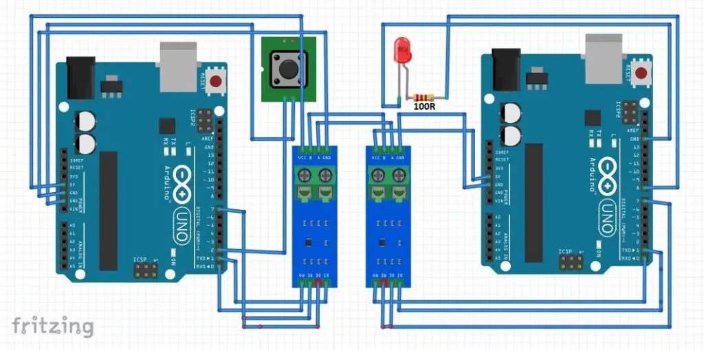
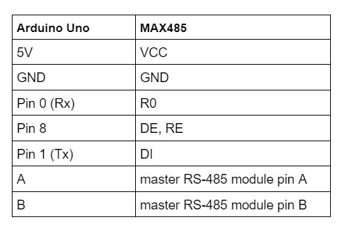
Connection description between Arduino and MAX485 ( master)
We also connect a push button to pin 2 of Arduino.
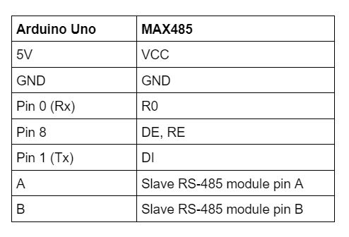
Connection description between Arduino and MAX485 ( slave)
We also connect a red led to pin 8 of Arduino with a 100 Ohm resistor in series.
Arduino and RS485 communication Code
We have written two Arduino sketch. One is for the master and another is for the slave. The Master will send a command and the slave will react according to the master’s command.
Arduino Code for Master
Open your Arduini IDE and go to File > new and create a new sketch. Copy the code below and paste it to the Arduino sketch and save it.
In this sketch, we will send a command “0” or “1” to the slave Arduino Board. We connect Arduino pin 2 to a push button. We configure an internal pull-up (normally high) for the push button.
.ino file for Arduino IDE
// Initialize the button state to 0
bool button_state=0;

void setup() {
  // put your setup code here, to run once:
  // arduino default baud rate for serial communication
  Serial.begin(9600);
  // DE,RE Controling pin of RS-485
  pinMode(7, HIGH);
  // pin 2 set as input with PULL-UP for button
  pinMode(2, INPUT_PULLUP);
  // DE,RE = HIGH, RS485 Transmit Enabled
  digitalWrite(7,HIGH);

}

void loop() {
  // put your main code here, to run repeatedly:
  // check if button is prasssed or not.
  //If digitalRead() function return 0 than the button is pressed-
  //because we use input pull-up for pin 2
  if(digitalRead(2) == 0){
    // wait 300ms to prevent debouncing
      delay(300);
      // evry time when button pressed button state will reverse it value from 0 to 1 or 1 to 0
      button_state = !button_state;
      // print the value in serial monitor
      Serial.print(button_state);
   }
}
Arduino Code for Slave
Again, open your Arduini IDE and go to File > new and create a new sketch. Copy the code below and paste it to the Arduino sketch and save it.
In this sketch, the slave Arduino receives the command from the master through the MAx485 module by using the RS485 protocol. We connect Arduino pin 8 to a LED. If the slave receives command “1” then LED will Turn ON and print “LED ON” to the Arduino IDE serial monitor or, if slave receives command “0” then LED will turn OFF and print “LED OFF” to the serial monitor.
.ino file for Arduino IDE
// Initialize the LED status
bool led_status;

void setup() {
  // arduino default baud rate for serial communication
  Serial.begin(9600);
  //DE,RE Controling pin of RS-485
  pinMode(7, OUTPUT);
  //pin 8 set as output for LED
  pinMode(8, OUTPUT);
   //DE,RE = 0, RS485 Receive Enabled
  digitalWrite(7,LOW);
}

void loop() {
  // wait untill all the bytes receive from data buffer
   while(Serial.available() > 0){
    // take the integer value from buffer (0 or 1)
      led_status = Serial.parseInt();
      // delay for 10 milliseconds
      delay(10);
      // check if command is 1
      if(led_status == 1){
        // LED pin high means LED ON
        digitalWrite(8,HIGH);
        Serial.println("LED ON");
       }
       // check if command "0"
       if(led_status == 0){
        // LED pin low means LED OFF
        digitalWrite(8,LOW);
        Serial.println("LED OFF");
      }
    }
}
Conclusion
RS485 serial data communication protocol is widely used in industries. In this tutorial, I expelled the basics of RS485 protocol and also interface it with Arduino through a TTL to RS485 module. I will write more articles about this topic soon.