
RS232 serial communication is a widely used protocol for transmitting data between devices. It allows devices to communicate over long distances using a simple interface. In this tutorial, we will explore how to use RS232 communication protocol with Arduino using MAX232 IC based RS232 to TTL module. For demonstration purposes, we will create a project that will ON or OFF a LED connected to Arduino from a Computer (Arduino ide serial terminal) by sending ON or OFF command through RS232.
Get 50% Off My Embedded Systems Book
Watch a short ad to unlock the special discount link for my book.
To know more about RS232 serial communication protocol, please read this article:
- RS485 Communication Protocol: Basics, Working Principle & Application
- Introduction to RS232 Serial Communication Protocol
You may also like reading:
- How to interface Arduino with RS485 (Modbus) protocol
- How to interface Modbus RTU (RS485) sensors with Arduino
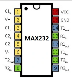
What is the MAX232?
MAX232 is an integrated circuit (IC) used for voltage level conversion in RS232 serial data communication. It allows devices operating at different voltage levels to communicate. It converts lower voltage signals to higher voltage levels required by RS-232 standard. Commonly used in interfaces between microcontrollers and PCs.
How Does the MAX232 Work?
The MAX232 IC utilizes internal circuitry to convert voltage levels between TTL and RS-232 standards. It incorporates charge pumps that generate the necessary positive and negative voltages required for reliable transmission and reception of RS-232 signals. This conversion process ensures effective communication between devices with different voltage requirements.
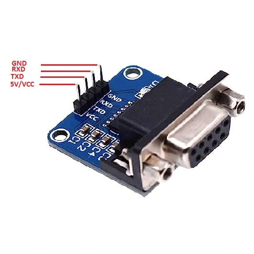
Pin Configuration of the MAX232 to TTL Converter Module
Interfacing Arduino with RS232 communication protocol: The project
Interfacing Arduino with the RS232 protocol enables seamless serial communication between devices operating at different voltage levels. The MAX232 module serves as a voltage level converter, bridging the gap between Arduino’s TTL logic levels and RS-232 levels used by many other devices. By establishing the connection and configuring the pins correctly, Arduino can transmit and receive data with RS-232 devices, expanding the possibilities for various electronic projects.
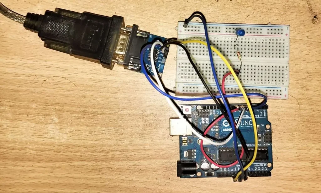
In this project, we will turn ON-OFF a LED by type some command in Arduino ide serial terminal. When we type “ON” to the serial terminal the LED will turn ON and when type “OFF” to serial terminal, LED will turn OFF. We will use RS232 to TTL converter and DB9 to USB converter for communication between Arduino and PC through RS232 communication protocol.
Component List for the project
| Component Name | Quantity | Purchase Link |
|---|---|---|
| Arduino Uno | 1 | Amazon |
| MAX232 RS232 to TTL Serial Port Converter | 1 | Amazon |
| USB to DB9 Cable (for communicate with PC) | 1 | Amazon |
| LED | 1 | Amazon |
| 220 Ohm Resistor | 1 | Amazon |
Affiliate Disclosure: When you click on links to make a purchase, this can result in this website earning a commission. Affiliate programs and affiliations include, but are not limited to Amazon.com
Pin Connecctions
The connection between Arduino and MAX232 module is shown below:
| Arduino Uno | MAX232 Module |
|---|---|
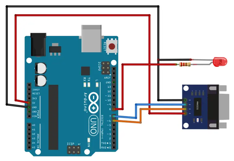
| Pin 7 (software selected TX pin) | TX pin |
| Pin 6 (software selected RX pin) | RX Pin |
| 5V pin of Arduino | Vcc |
| Ground pin of Arduino | Ground Pin |
Circuit Diagram of This Project
Arduino code and its explanation
The provided code is an Arduino sketch that demonstrates the use of the MAX232 module for serial communication between an Arduino board and external devices (i.e. PC). Let’s go through the code step by step:
- The necessary libraries header files are included: SoftwareSerial.h, string.h, and stdio.h.
- Global variables are declared: recv_char to store the received characters, recv_str as a character array to store the received string, and i as a counter for the string array.
- The SoftwareSerial object mySerial is created, specifying the RX and TX pins (pin 6 and pin 7) respectively to establish communication with the MAX232 module.
- The LED pin (pin 8) is defined as an output pin.
In the `setup()` function:
- The baud rate for the Arduino’s hardware serial port is set to 2400 using Serial.begin().
- A message is printed to the Arduino’s serial port to indicate that it is ready.
- The baud rate for the mySerial SoftwareSerial port is set to 2400 using mySerial.begin().
- The LED pin is configured as an output and initially set to a LOW state.
The `loop()` function is the main execution loop of the program:
- It checks if there is incoming data available from the MAX232 module using mySerial.available().
- If data is available, the received character is read into recv_char.
- If the received character is a carriage return (‘\r’), it indicates the end of a command or message.
- The characters received before the carriage return are stored in recv_str, which is then null-terminated.
- If the received string matches “ON”, the LED pin is set to HIGH, and “high” is printed to the Arduino’s serial monitor.
- If the received string matches “OFF”, the LED pin is set to LOW, and “low” is printed to the Arduino’s serial monitor.
- The received string is also printed to the Arduino’s serial port.
- The variables are reset for the next incoming message by ‘memeset’.
- If the received character is not a carriage return, it is added to the recv_str array.
Additionally, the code checks for incoming data from the Arduino’s serial port (`Serial.available()`).
- If data is available, the received character is read into recv_char.
- If the received character is a carriage return (‘\r’), it indicates the end of a command or message.
- The characters received before the carriage return are stored in recv_str, which is then null-terminated.
- The received string is sent to the MAX232 module using mySerial.println().
- The variables are reset for the next incoming message.
Full code
Arduino Ide .ino file
#include <SoftwareSerial.h>
#include <string.h>
#include <stdio.h>
uint8_t recv_char;
char recv_str[20];
int i=0;

SoftwareSerial mySerial(6, 7); // RX, TX
#define LED 8
void setup()
{

  Serial.begin( 2400 );                   //Set the baund rate as 2400 for arduino serial
  Serial.println("USB Serial is ready");
  mySerial.begin( 2400 );                 // set the baund rate for the SoftwareSerial port
  pinMode(LED, OUTPUT);
  digitalWrite(LED,LOW);
}

void loop()
{
  if ( mySerial.available() )
  {
    recv_char =  mySerial.read();
    if(recv_char == '\r'){
      recv_str[i] = '\0';
      if(!strcmp(recv_str, "ON")){
        digitalWrite(LED,HIGH);
        Serial.println("high");
      }
      if(!strcmp(recv_str, "OFF")){
        digitalWrite(LED,LOW);
        Serial.println("low");
      }
      Serial.println(recv_str);       // Write the serial from MAX3232 to Arduino serial
      i=0;
      memset(recv_str, 0, sizeof(recv_str));
    }
    else{
		  if(recv_char == '\r' || recv_char == '\n'){
		}
      else{
		    recv_str[i++] = recv_char;
		    }
    }

  }

  if ( Serial.available() )
  {
   recv_char =  Serial.read();
    if(recv_char == '\r'){
      recv_str[i] = '\0';
      mySerial.println(recv_str);       // Write the serial from MAX3232 to Arduino serial
      i=0;
      memset(recv_str, 0, sizeof(recv_str));
    }
    else{
		  if(recv_char == '\r' || recv_char == '\n'){
		}
      else{
		    recv_str[i++] = recv_char;
		    }
    }

  }
}