
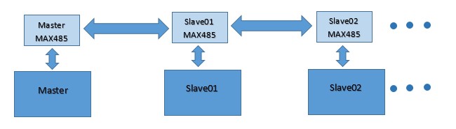
This tutorial will discuss how we can communicate between multiple (3 to 32) ESP32 devices using RS485 physical layer. We will follow the Modbus master-slave communication method and build a data communication system using three ESP32 where one ESP32 acts as master and other two are slave in Arduino IDE.
You may also like reading:
- How to interface Raspberry Pi Pico with RS485 Protocol
- How to interface STM32 with RS485 (Modbus) sensors
- Introduction to RS232 Serial Communication Protocol
- How to interface Arduino with RS485 (Modbus) protocol with example code
- How to interface Modbus RTU (RS485) sensors with Arduino
Our other ESP32-related tutorials are:
- How to install ESP32 Board in Arduino IDE
- How to interface ESP32 with RS485 (Modbus) sensors with example code
- Esp32 LoRa tutorial using Arduino IDE with example code
- ESP32 LoRaWAN Gateway tutorial with Sensor Node
What is rs485?
The RS485 protocol is a standard for serial communication over long distances. It uses differential signaling to transmit data and supports multiple devices on a single bus. The RS485 protocol is widely used in industrial automation, building automation, and other applications where multiple devices need to communicate with each other.
If you want to know more about Modbus and RS485 visit our previous article.
Communication between multiple ESP32
To communicate multiple ESP32 devices using the RS485 protocol, you need to choose an RS485 transceiver. The RS485 transceiver is a critical component that converts the UART signal to the RS485 protocol. You can choose from a wide range of RS485 transceivers available in the market, such as MAX485, SN75176, etc. In this tutorial we will use MAX485 TTL to RS485 converter. You need to connect the RS485 transceiver to the ESP32 GPIO pins.
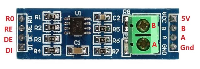
The MAX485 is used to communicate between master and slaves. The main feature of this module is it can communicate at the range of about 1 Kilometer.
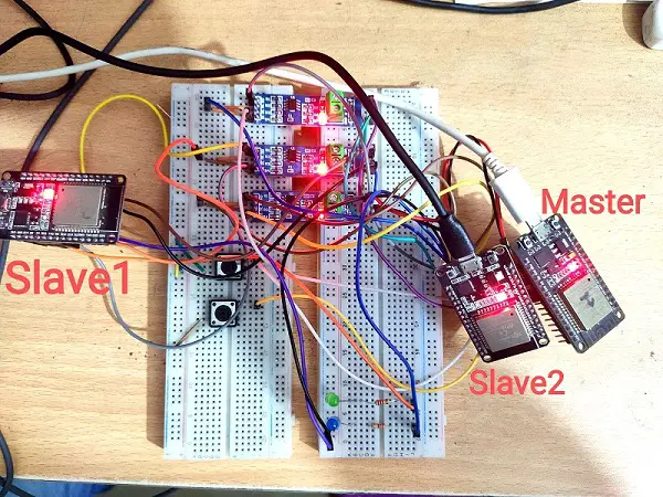
Communicate multiple ESp32 via RS485 : The Project
In this example project, we will use three ESP32. One for master and two for Slave. Two button are connected with master, one for slave one and another for slave two. Two LEDs are connected with slave one and slave two respectively. When button one is pressed LED 1 will be glow and when button two is pressed LED 2 will be glow and each slave send a feedback to the master.
Component list
You need these components for this project
| Component Name | Quantity | Purchase Link |
|---|---|---|
| ESP32 development board | 3 | Amazon |
| Push button | 2 | Amazon |
| MAX485 TTL to RS485 converter module | 3 | Amazon |
| Breadboard | 3 | Amazon |
| Jumper Wire pack | 1 | Amazon |
| LED | 1 | Amazon |
| 5V power supply | 2 | Amazon |
| 220 ohm Resistor | 2 | Amazon |
For troubleshooting, some extremely useful test equipment
| Equipment Name | Purchase Link |
|---|---|
| Best Oscilloscope for Professionals | Amazon |
| Best Oscilloscope for Beginners | Amazon |
| Logic Analyzer | Amazon |
| Best Budget Multimeter | Amazon |
| Adjustable Bench Power Supply | Amazon |
Affiliate Disclosure: When you click on links to make a purchase, this can result in this website earning a commission. Affiliate programs and affiliations include, but are not limited to Amazon.com
Circuit diagram
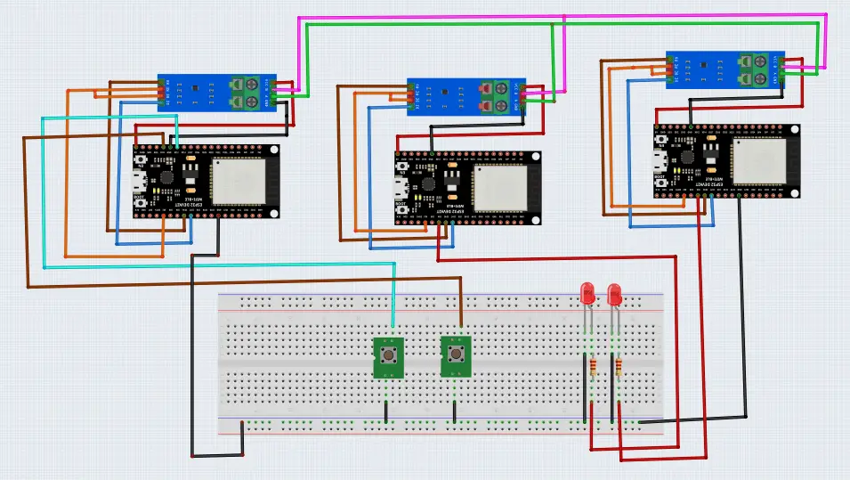
Pin connection
Pin connection between ESP32 and MAX485 is shown below:
[wptb id=865]
Please Note: The A and B pin of all MAX485 are connected together.
Pin connection between Master ESP32 and Button is shown below:
[wptb id=869]
Pin connection between Slave ESP32 and LED is shown below:
[wptb id=870]
Code Analysis of Master ESP
First few lines are header files of Arduino IDE. We know that ESP32 has total three hardware supported serial interfaces known as UART0, UART1 and UART2.
[wptb id=871]
Hence, we are using UART 2 in our project. For this reason, HardwareSerial.h is used.
#include <Arduino.h>
#include <string.h>
#include <HardwareSerial.h>
HardwareSerial SerialPort(2);
This lines for defining two slave’s numbers. These slave numbers are send to serial data line when slave number is matched with particular slave then this slave will response.
int slave_1_id = 1;
int slave_2_id = 2;
Define two push button. Button number 1 for slave 01 and button number 2 for slave 02. when one of the button is pressed a slave number send to the data line. For example, if button 1 is pressed then slave_1_id = 1 will send to serial port and slave 01 will response. Also define a Enable pin for selecting data send and receive mode.
const int BUTTON_PIN_01 = 12;
const int BUTTON_PIN_02 = 13;
const int Enable =  2;
In setup function, select bund rate 115200 by Serial.begin(115200) for UART 0 which is communicate between Computer and Master ESP32. Same bund is selected by SerialPort.begin(115200, SERIAL_8N1, 16, 17) for UART 2 that is used to communicate between one to another ESP32. Set the enable pin as output and makes it Low. There are two mode of MAX485 one is transmission and another is receiving mode. To keep MAX485 in transmission mode DE and RE pins of MAX485 must be High and for receiving mode DE and RE pins must be Low. We keep it receiving mode initially. Also, enable input pullup for button 1 and button 2.
void setup() {
  Serial.begin(115200);
  SerialPort.begin(115200, SERIAL_8N1, 16, 17);
  //SerialPort.setTimeout(250);
  pinMode(Enable, OUTPUT);
  digitalWrite(Enable, LOW);
  pinMode(BUTTON_PIN_01, INPUT_PULLUP);
  pinMode(BUTTON_PIN_02, INPUT_PULLUP);
}
In the loop function when button 01 is pressed enable pin goes high to keep MAX485 in transmission mode because our aim is to transmit some data to slave. By SerialPort.flush() function we send two or more data serially and data is received oldest one first pattern. First a slave number is sent and then a data, in this case we send a string “ON”. Enable pin makes low to keep Max485 in receiving mode to receive response from slave 01.
void loop() {
     /* Master Program  */
     if(digitalRead(BUTTON_PIN_01) == 0){
      delay(500);
      digitalWrite(Enable, HIGH);
      SerialPort.print(slave_1_id);
      SerialPort.print("ON");
      SerialPort.flush();
      digitalWrite(Enable, LOW);
      //digitalWrite(BUTTON_PIN_01, HIGH);
     }
When we press button02 almost similar thing will happen. At this time Slave 2 will response.
      if(digitalRead(BUTTON_PIN_02) == 0){
        delay(500);
        digitalWrite(Enable, HIGH);
        SerialPort.print(slave_2_id);
        SerialPort.print("ON");
        SerialPort.flush();
        digitalWrite(Enable, LOW);
      }
At the end when slave send a response massage we will see a feedback message from the slave01 or slave02. SerialPort.available() means UART2 find a data and if data is available then print a feedback message on the serial monitor of Arduino IDE.
if(SerialPort.available()){
    Serial.println(SerialPort.readString());
}
Full code of master ESP32
#include <Arduino.h>
#include <string.h>
#include <HardwareSerial.h>
HardwareSerial SerialPort(2);

int slave_1_id = 1;
int slave_2_id = 2;

const int BUTTON_PIN_01 = 12;
const int BUTTON_PIN_02 = 13;
const int Enable =  2;

void setup() {
  Serial.begin(115200);
  SerialPort.begin(115200, SERIAL_8N1, 16, 17);
  //SerialPort.setTimeout(250);
  pinMode(Enable, OUTPUT);
  digitalWrite(Enable, LOW);
  pinMode(BUTTON_PIN_01, INPUT_PULLUP);
  pinMode(BUTTON_PIN_02, INPUT_PULLUP);
}

void loop() {
     /* Master Program  */
     if(digitalRead(BUTTON_PIN_01) == 0){
      delay(500);
      digitalWrite(Enable, HIGH);
      SerialPort.print(slave_1_id);
      SerialPort.print("ON");
      SerialPort.flush();
      digitalWrite(Enable, LOW);
      //digitalWrite(BUTTON_PIN_01, HIGH);
     }


      if(digitalRead(BUTTON_PIN_02) == 0){
        delay(500);
        digitalWrite(Enable, HIGH);
        SerialPort.print(slave_2_id);
        SerialPort.print("ON");
        SerialPort.flush();
        digitalWrite(Enable, LOW);
      }

      if(SerialPort.available()){
        Serial.println(SerialPort.readString());
      }
      delay(100);

  }
Code Analysis of Slave 01
These few lines are almost similar with master code. So can skip these lines for now.
 #include <HardwareSerial.h>
HardwareSerial SerialPort(2);

const int Enable =  2;
take an integer that store slave number. Define a LED pin for LED 01.
const int SlaveNumber = 1;
int Slave;
const int LED = 4;
//In setup function makes LED and Enable pin low and set as output.
void setup() {
  pinMode(Enable, OUTPUT);
  pinMode(LED, OUTPUT);
  digitalWrite(Enable, LOW);
  digitalWrite(LED, LOW);
}
In the loop function when serial find a data using SerialPort.available() function check the slave number. If slave number match with the incoming slave number form master using SerialPort.parseInt() function, then it will compare the incoming string using SerialPort.readString(). If incoming string function match with the condition string, then a LED will glow. And a feedback message sends to the master using SerialPort.println. At the end “Slave 1 is triggered” message will show on serial monitor of Arduino IDE.
void loop()
{
  digitalWrite(Enable, LOW);
  if(SerialPort.available())
  {
      Slave = SerialPort.parseInt();
      Serial.println(Slave);
      if(Slave == SlaveNumber)
      {
        String command = SerialPort.readString();
          Serial.println(command);
           if(command == "ON")
           {
              digitalWrite(LED, HIGH);
              delay(2000);
              digitalWrite(LED, LOW);
            }
              digitalWrite(Enable, HIGH);
              SerialPort.println("Slave 1 is triggered");
           }
          // Serial.println("loop");
        }
    }
Full code of slave 01
#include <HardwareSerial.h>
HardwareSerial SerialPort(2);
const int Enable =  2;
const int SlaveNumber = 1;
int Slave;
const int LED = 4;
void setup()
{
  Serial.begin(115200);
  SerialPort.begin(115200, SERIAL_8N1, 16, 17);
  SerialPort.setTimeout(250);
  pinMode(Enable, OUTPUT);
  pinMode(LED, OUTPUT);
  digitalWrite(Enable, LOW);
  digitalWrite(LED, LOW);
}
void loop()
{
  digitalWrite(Enable, LOW);
  if(SerialPort.available())
  {
      Slave = SerialPort.parseInt();
      Serial.println(Slave);
      if(Slave == SlaveNumber)
      {
        String command = SerialPort.readString();
          Serial.println(command);
           if(command == "ON")
           {
              digitalWrite(LED, HIGH);
              delay(2000);
              digitalWrite(LED, LOW);
            }
              digitalWrite(Enable, HIGH);
              SerialPort.println("Slave 1 is triggered");
           }
           //Serial.println("loop");/
        }
    }
Code Analysis of Slave 02
Almost similar code like slave 01. Just one change in slave number that is const int SlaveNumber = 2.
Full code of slave 02
#include <HardwareSerial.h>
HardwareSerial SerialPort(2);
const int Enable =  2;
const int SlaveNumber = 2;
int Slave;
const int LED = 4;
void setup()
{
  Serial.begin(115200);
  SerialPort.begin(115200, SERIAL_8N1, 16, 17);
  SerialPort.setTimeout(250);
  pinMode(Enable, OUTPUT);
  pinMode(LED, OUTPUT);
  digitalWrite(Enable, LOW);
  digitalWrite(LED, LOW);
}
void loop()
{
  digitalWrite(Enable, LOW);
  if(SerialPort.available())
  {
      Slave = SerialPort.parseInt();
      Serial.println(Slave);
      if(Slave == SlaveNumber)
      {
        String command = SerialPort.readString();
          Serial.println(command);
           if(command == "ON")
           {
              digitalWrite(LED, HIGH);
              delay(2000);
              digitalWrite(LED, LOW);
            }
              digitalWrite(Enable, HIGH);
              SerialPort.println("Slave 2 is triggered");
           }
           //Serial.println("loop");/
        }
    }