
In this tutorial, we will interface ESP32 with LoRa SX1278 (Ra-02) module using Arduino IDE. We will create a real-world example project that turns ON-OFF a led wirelessly over LoRa for the demonstration. We also build a LoRa sender and LoRa receiver circuit for this project using ESP32 and SX1278 (Ra-02) modules. So, let’s get started,
Get 50% Off My Embedded Systems Book
Watch a short ad to unlock the special discount link for my book.
Our other ESP32 related tutorials are:
- How to install ESP32 Board in Arduino IDE
- How to interface ESP32 with RS485 (Modbus) sensors with example code
- ESP32 LoRaWAN Gateway tutorial with Sensor Node
- IoT Based Energy Monitoring System using ESP32 and Firebase
What is LoRa?
LoRa (means Long Range) is a wireless communication technology with low power consumption for long-range communication. It is a proprietary technology developed by Semtech and is used for IoT applications, smart cities, and more. LoRa uses a spread-spectrum technique to enable long-range communication over several kilometers in urban environments and over 10 kilometers in rural areas.

Lora Frequency
LoRa technology uses unlicensed frequencies and they are available worldwide. These are the three most widely used frequencies:
- 433 MHz for Asia
- 915 MHz for North America
- 868 MHz (Europe)
Check this link to find the frequencies used in your country
To read more about Lora and Lorawan technology, please check the following tutorial:
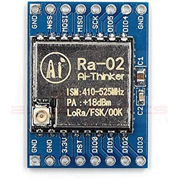
Lora SX1278 (Ra-02) Module
The SX1278 module is a low-cost, low-power, long-range transceiver module based on the LoRa technology. It operates in the 433MHz frequency band and can transmit up to 10 km of data in open spaces. The module includes an SPI interface for communication with microcontrollers like Arduino, Esp32, or Stm32.
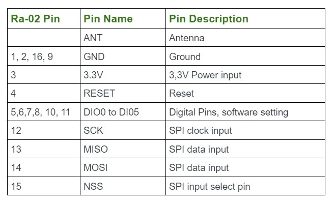
LoRa SX1278 (Ra-02) Pinout
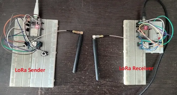
Interfacing ESP32 with LoRa SX1278 (Ra-02) Module (The Project):
In this section of the tutorial, we will build a real-world wireless communication project by using LoRa and ESP32. We will control a LED wirelessly by pressing a push button. For this project, need to build two circuits and we called them LoRa Sender (transmitter) and LoRa receiver circuit. So, let’s build the project,
Component List for the Project
| Component Name | Quantity | Purchase Link |
|---|---|---|
| Esp32 development board | 2 | Amazon | AliExpress |
| Push button | 1 | Amazon | AliExpress |
| LoRa Module | 2 | Amazon | AliExpress |
| Breadboard | 2 | Amazon | AliExpress |
| Jumper Wire pack | 1 | Amazon | AliExpress |
| 5V power supply | 1 | Amazon | AliExpress |
| LED | 1 | Amazon | AliExpress |
| 220 ohm Resistor | 1 | Amazon | AliExpress |
Affiliate Disclosure: When you click on links to make a purchase, this can result in this website earning a commission.
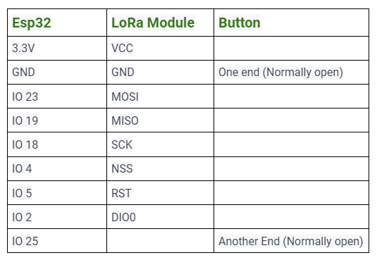
Step One: Connect the Hardware
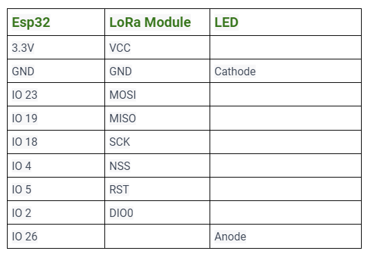
The first step is to connect the hardware components. Connect the LoRa SX1278 module to the ESP32 development board using the following pin connections for both the sender and receiver circuit:
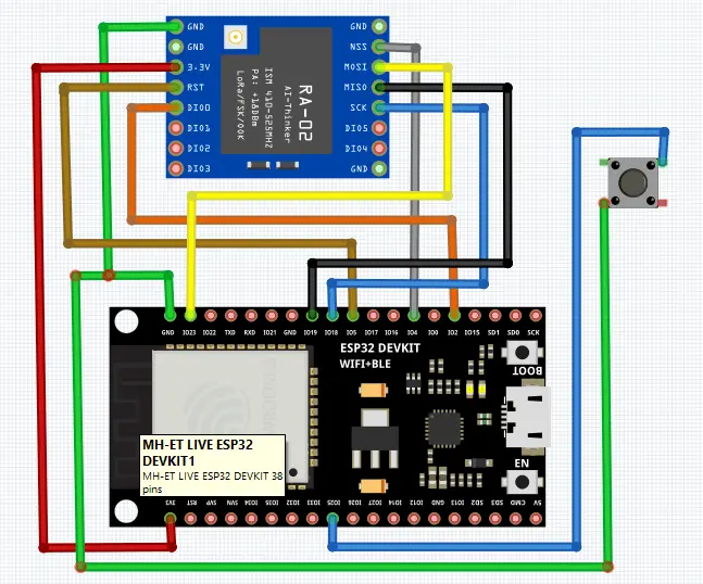
LoRa sender circuit connection:
Circuit Diagram of LoRa Sender:
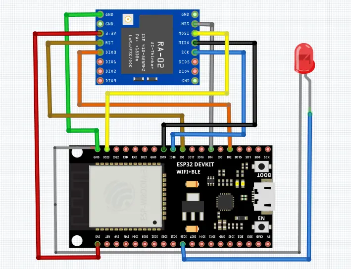
LoRa Receiver circuit connection:
Circuit Diagram of LoRa receiver:
Step Two: Install Required Libraries for Arduino Ide
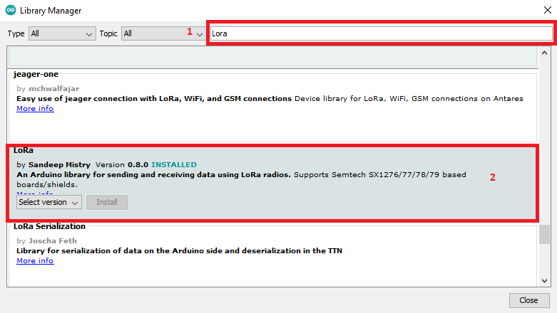
The next step is to install the required library for the ESP32 and the LoRa SX1278 module. Open the Arduino IDE then go to Tools > Manage Libraries and install the following library:
- LoRa by Sandeep Mistry
Step Three: Write the Code
After connecting the hardware and installing the libraries, we can now write the code for the ESP32 to communicate with the LoRa SX1278 module.
LoRa sender code:
The following code sends a message “on” or “off” over LoRa. When the push button is pressed an interrupt is triggered and ESP32 sends “on” over LoRa sender to receiver. When the button is again pressed it sends “off” to the receiver.
//Incuding arduino default SPI library
#include <SPI.h>
//Incuding LoRa library
#include <LoRa.h>

//define the pins used by the transceiver module
#define NSS 4
#define RST 5
#define DI0 2
#define BUTTON 25

//this variable is for update the status of the push button
uint8_t button_status = 0;

// this function is called the Interrupt Setvice Routine (ISR).
// When button is pressed, this function will trigger.
// and, update the "button_status" variable to (1 to 0) or (0 to 1)
void IRAM_ATTR ISR() {
  Serial.println("interrupt triggered");
  //every time the interrupt is triggered,
  // button_status value will inverse (0 to 1) or (1 to 0)
  button_status = !button_status;
}

void setup() {
  //initialize Serial Monitor
  Serial.begin(115200);
  //take pin 25 as INPUT with PULL-UP.
  //PULLUP means pin 15 is normally high. When button pressed it gets LOW
  pinMode(BUTTON, INPUT_PULLUP);
  //Attaching an Interrupt to pin 25 (BUTTON pin)
  // when button goes (high to low) state, then interrupt will triggered
  attachInterrupt(BUTTON, ISR, FALLING);
  Serial.println("LoRa Sender");
  //setup LoRa sender
  LoRa.setPins(NSS, RST, DI0);
  //Select the frequency accordng to your location
  //433E6 for Asia
  //866E6 for Europe
  //915E6 for North America
  while (!LoRa.begin(433E6)) {
    Serial.println(".");
    delay(500);
  }
  // Change sync word (0xF1) to match the receiver LoRa
  // This code ensure that you don't get LoRa messages
  // from other LoRa transceivers
  // ranges from 0-0xFF
  LoRa.setSyncWord(0xF1);
  Serial.println("LoRa Initializing Successful!");
}

void loop() {
  Serial.print("Sending packet: ");
  //If the button_status is 1, Send LoRa packet "on" to receiver LoRa
  if(button_status == 1){
      LoRa.beginPacket();
      LoRa.print("on");
      LoRa.endPacket();
      Serial.println("sent lora to on");

   }
    //If the button_status is 0, Send LoRa packet "off" to receiver LoRa
   if(button_status == 0){
      LoRa.beginPacket();
      LoRa.print("off");
      LoRa.endPacket();
      Serial.println("sent lora to off");
   }
   delay(500);
}
Lora receiver code:
The following code receives the message “on” or “off” over the LoRa sender and turns ON-OFF the LED accordingly.
//Incuding arduino default SPI library
#include <SPI.h>
//Incuding LoRa library
#include <LoRa.h>

//define the pins used by the transceiver module
#define NSS 4
#define RST 5
#define DI0 2
#define LED 26

String LoRaData;

void setup() {
  //initialize Serial Monitor
  Serial.begin(115200);
  //set pin  26 as output for led
  pinMode(LED, OUTPUT);
  Serial.println("LoRa Sender");

  //setup LoRa transceiver module
  LoRa.setPins(NSS, RST, DI0);

  //Select the frequency accordng to your location
  //433E6 for Asia
  //866E6 for Europe
  //915E6 for North America
  while (!LoRa.begin(433E6)) {
    Serial.println(".");
    delay(500);
  }
  // Change sync word (0xF1) to match the receiver LoRa
  // This code ensure that you don't get LoRa messages
  // from other LoRa transceivers
  // ranges from 0-0xFF
  LoRa.setSyncWord(0xF1);
  Serial.println("LoRa Initializing Successful!");
}

void loop() {
  // LoRa data packet size received from LoRa sender
   int packetSize = LoRa.parsePacket();
   // if the packer size is not 0, then execute this if condition
  if (packetSize) {
    // received a packet
    Serial.print("Received packet: ");

    // receiving the data from LoRa sender
    while (LoRa.available()) {
      LoRaData = LoRa.readString();
    }
    Serial.println(LoRaData);

  }

  // if the received data is "true", then LED will ON
  if(LoRaData == "true"){
      digitalWrite(LED, HIGH); // LED ON
      delay(5);
    }
    // if the received data is "false", then LED will OFF
    if(LoRaData == "false"){
      digitalWrite(LED, LOW); // LED OFF
      delay(5);
    }
}