
In this tutorial, we will explain the basic principles of the Lora communication technique, and how LoRa can be used with the Arduino for IoT projects using the Arduino IDE. To get you started, we will also show you how to create a simple LoRa Sender and LoRa Receiver with the SX1278 (Ra-02) Lora module with the help of a project which ON-OFFs a LED wirelessly using an LDR (Light Dependent Resistor).
If you want to interface ESP32 with LoRa, please check the following tutorials:
- Esp32 LoRa tutorial using Arduino IDE with example code
- ESP32 LoRaWAN Gateway tutorial with Sensor Node
Our other Arduino related tutorials are:
- Arduino with RS485 (Modbus) protocol with example code
- Interfacing Arduino with Bluetooth Module (HC-05)
- How to interface Modbus RTU (RS485) sensor with Arduino
What is LoRa?
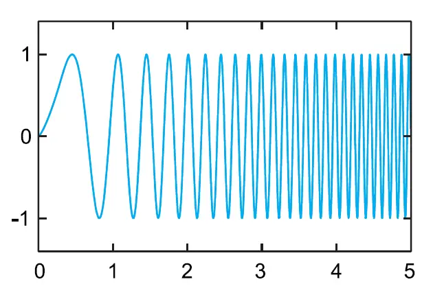
LoRa stands for Long Range. It is a wireless data communication technology based on spread spectrum modulation techniques derived from chirp spread spectrum (CSS) technology. It was first introduced by Cycleo, a company in Grenoble, France, and later acquired by Semtech.
The spread spectrum modulation technique provides secure communications by spreading the signal over a large frequency band and allows long-range communication with low bandwidth (which means low data rate) without consuming much power.
Lora comes in different frequency ranges. It transmits over license-free megahertz radio frequency bands: There are the most common frequency bands are:
- 433 MHz (Asia)
- 868 MHz (Europe)
- 915 MHz (North America)
Also, note that every country has its unlicensed frequency range. anyone can freely use them without having to get a license. Please check the link for available unlicensed frequencies used in your country.
LoRa Range
LoRa could achieve a distance up to 3 miles (5 kilometers) in urban areas, and up to 10 miles (15 kilometers) or more in rural areas (line of sight).
LoRa Applications
LoRa is the de facto technology for IoT based on its widespread adoption and will be responsible for connecting IoT devices. LoRa is very flexible because of its long-range and low-power features which also makes it perfect for battery-operated sensors and low-power applications in various fields like:
- industrial IoT (IIoT)
- smart environment monitoring
- smart agriculture
- smart homes and cities
- smart utilities and metering
- smart supply chain and logistics
Please note that Lora is not suitable where needs high data-rate transmission capabilities and frequent transmissions.
LoRa Topologies:
We can connect Lora devices by using two methods and they are
- Point to Point method
- Star Topology (a Lora communication network)
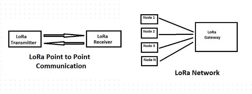
In this tutorial, we will demonstrate a point-to-point communication method between two Lora devices by using Arduino and sx1278 (Ra-02) Lora module.
But you can build a Lora network (Star Topology) using LoRaWAN.
What is LoraWAN?
LoRaWAN is a Low Power, Wide Area (LPWA) networking protocol designed to wirelessly connect battery-operated ‘things’ to the Internet in regional, national or global networks, and targets key Internet of Things (IoT) requirements such as bi-directional communication, end-to-end security, mobility and localization services. For more information, you can follow the Lora Alliance website.
Interfacing Lora sx1278 with Arduino Uno
In this part of the article, we will show you how to send and receive data between two Lora modules using Arduino IDE. We will use Arduino Uno as a microcontroller unit to interface with LoRa. To demonstrate the technology we will build a simple project that will control a led (ON or OFF) according to the LDR (Light Dependent Resistor) value wirelessly.
Component List
To follow the project you will need several components and they are:
| Component List | Quantity | Purchase Link |
|---|---|---|
| Arduino Uno | 2 | Amazon |
| LDR Sensor | 1 | Amazon |
| LoRa Module | 2 | Amazon |
| Breadboard | 2 | Amazon |
| Jumper Wire pack | 1 | Amazon |
| LED | 1 | Amazon |
| 220 Ohm Resistor | 1 | Amazon |
| 100K | 1 | Amazon |
For troubleshooting, some extremely useful test equipment
| Equipment Name | Purchase Link |
|---|---|
| Best Oscilloscope for Professionals | Amazon |
| Best Oscilloscope for Beginners and Students | Amazon |
| Logic Analyzer | Amazon |
| Best Budget Multimeter | Amazon |
| Adjustable Bench Power Supply | Amazon |
Affiliate Disclosure: When you click on links to make a purchase, this can result in this website earning a commission. Affiliate programs and affiliations include, but are not limited to Amazon.com
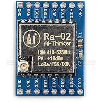
LoRa SX1278 (Ra-02) Module
Ra-02 wireless transmission module based on SEMTECH’s SX1278 wireless transceiver. It follows advanced LoRa spread spectrum technology, with a high communication distance of more than 10 kilometers and a frequency is 433MHz. It has the ability of anti-jamming and has the function of air wake-up Consumption. The SX1278 RF module is mainly used for long-range spread spectrum communication, and it can resist Minimizing current consumption. The SX1278 has a high sensitivity of -148 dBm with a power output of +20 dBm, a long transmission distance, and high reliability.
Here is the pinout of Lora Ra-02:
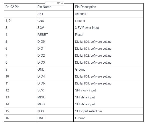
Antenna is one of the important components of LoRa modules. It is mandatory to use an antenna while operating the Lora modules otherwise the output transmitting power will damage the Module. I will use a 433MHz antenna for the Ra-02 module because it is rated 433MHz.
What is LDR?
LDR (Light Dependent Resistor) is a special type of resistor that works on the photoconductivity principle, which means that resistance changes according to light intensity. Its resistance decreases with an increase in the power of light. It is often used as a light sensor or used in areas where we need to have light sensitivity.
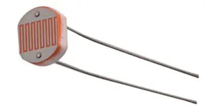
In this article, we use LDR as a light sensor to ON or OFF the LED light wirelessly. We connect LDR in the transmitter and LED in the receiver.
Circuit Connections
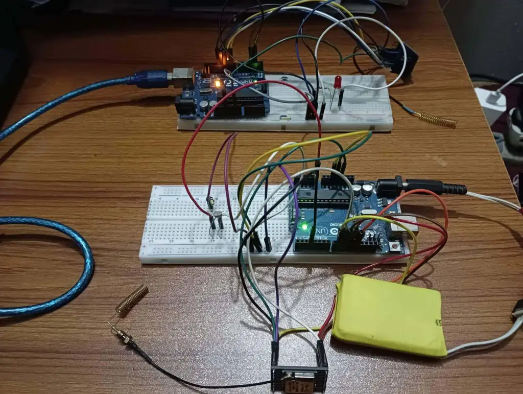
In this section of the article, We will show you how to connect LoRa (Ra-02) to Arduino Uno with the help of the connection diagram and pin description table. For demonstration purposes, we will build two circuits.
One is for the transmitter end and another is for the receiver end. At the transmitter end, we also connect an LDR sensor which detects the intensity of the light and sends the information to the receiver end wirelessly. On the receiver side, we also connect a LED to the Arduino. We just collect the LDR value from the transmitter side wirelessly and ON-OFF our LED accordingly.
we have powered the transmitter circuit with a 5 Volt Li-ion battery and powered the receiver circuit from a laptop USB port.
Arduino LoRa transmitter connection
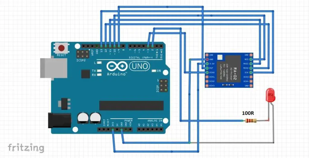
In the transmitter side, I will connect LoRa (Ra-02) to Arduino Uno through SPI communication protocol. Because Ra-02 module supports SPI protocol. The connection is shown in the circuit below:
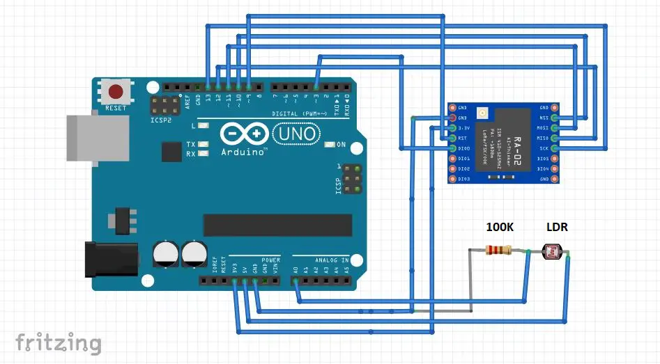
I also connect an LDR sensor to the A0 pin of Arduino. We will read analog values (0 to 1024) from LDR(A0 pin). Then, send the value through LoRa wirelessly to our Receiver end.
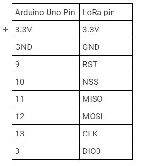
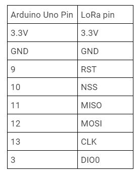
The connection and pin description of Arduino and Lora are shown in the table below:
Arduino LoRa receiver connection
Receiver side connection is same as trimester side. We just add a LED to pin D2 of Arduino. All other connections are the same. The circuit diagram is shown below:
The connection and pin description of Arduino and Lora are shown in the table below:
Preparing the Arduino IDE
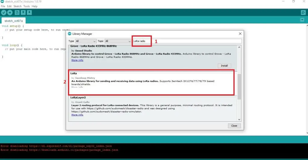
After circuit connection, Our next step to prepare Arduino IDE. In this project we will use arduino-LoRa library by Sandeep Mistry. You can download the library from GitHub and add to your Arduino IDE or you can install the library from Arduino IDE.
To install, the library from Arduino IDE, Open your IDE and go to Sketch -> Include Library -> Manage Libraries and search for “LoRa Radio”. Then install the library called LoRa by Sandeep Mistry. After installation complete restart your Arddiuino IDE.
Arduino LoRa Transmitter Code
After Prepared the circuit and Arduino IDE copy the code to your Arduino IDE. Then build and upload the code to your Arduino microcontroller.
.ino file for Arduino IDE
/*
 * loRa sender code
 * Author: EmbeddedThere.com
 */

#include <SPI.h>
#include <LoRa.h>

//define the pins used by the transceiver module
#define NSS 10
#define RST 9
#define DIO0 3

// LDR connect to Arduino Analog pin A0
#define LDR A0

int ldr_value = 0;

void setup() {
  //Initialize the serial monitor
  Serial.begin(9600);
  while (!Serial);

  // take pin R0 as input
  pinMode(LDR, INPUT);

  Serial.println("LoRa Sender");

  //setup LoRa NSS, RST and DIO0 pins for transceiver module
  LoRa.setPins(NSS, RST, DIO0);

  // select the frequency according to your module. most commom frequences are 433E6,866E6 and 915E6
  if (!LoRa.begin(433E6)) {
    Serial.println("Starting LoRa failed!");
    while (1);
  }

  // Change sync word (0xF3) to match the receiver
  // This is a unique message id. The sync word use to assures taht LoRa messages don't match to other LoRa transceivers
  // 0-0xFF range
  LoRa.setSyncWord(0xF3);
  Serial.println("LoRa Initializing OK!");
}

void loop() {
  // map the analog value (0-1024) to (0-055)
  int ldr_value = map(analogRead(LDR),0,1024,0,255);
  Serial.print("Sending packet: ");
  Serial.print("LDR value: ");
  Serial.println(ldr_value);

  // send packet
  LoRa.beginPacket();
  LoRa.print(ldr_value);
  LoRa.endPacket();

  delay(2000);
}
Arduino LoRa Receiver Code
.ino file for Arduino IDE
/*
 * LoRa Receiver
 * Author: EmbeddedThere.com
 */

#include <SPI.h>
#include <LoRa.h>

//define the pins used by the transceiver module
#define NSS 10
#define RST 9
#define DIO0 3

// LED Pin
#define LED 2

String loraString = "";
int val = 0;

void setup() {
  //Initialize the serial monitor
  Serial.begin(9600);
  while (!Serial);

  // LED configure for output
  pinMode(LED, OUTPUT);

  Serial.println("LoRa Receiver");

   //setup LoRa NSS, RST and DIO0 pins for transceiver module
  LoRa.setPins(NSS, RST, DIO0);

  // select the frequency according to your module. most commom frequences are 433E6,866E6 and 915E6
  if (!LoRa.begin(433E6)) {
    Serial.println("Starting LoRa failed!");
    while (1);
  }

  // Change sync word (0xF3) to match the receiver
  // This is a unique message id. The sync word use to assures taht LoRa messages don't match to other LoRa transceivers
  // 0-0xFF range
  LoRa.setSyncWord(0xF3);
  Serial.println("LoRa Initializing OK!");
}

void loop() {
  // try to parse packet
  int packetSize = LoRa.parsePacket();
  if (packetSize) {
    // received a packet
    Serial.print("Received packet '");

    // read packet
    while (LoRa.available()) {
      // read the message from lora transmitter
      int data = LoRa.read();
      // creating a string of message
      loraString += (char)data;

    }

    //convert the string to integer and store it to a integer variable
    val = loraString.toInt();
    loraString = ""; // empty the string

    // print RSSI of packet
    Serial.print("' with RSSI ");
    Serial.println(LoRa.packetRssi());
  }
  Serial.println(val);

  if(val > 100){
      Serial.println("LED ON");
      // If LRD value is greater tham 100 LED will ON
      digitalWrite(LED, HIGH);
    } else{
      Serial.println("LED OFF");
      // If LRD value is less tham 100 LED will OFF
      digitalWrite(LED, LOW);
    }

}
Result
When we decrease the intensity of light by putting our hand or something on the top of the LDR sensor, this causes an increase in the resistance of the LDR sensor and the analog pin produces a value accordingly. This value sends by the transmitter circuit to the receiver circuit wirelessly and LED turns ON. When we take away our hand, the resistance of the LDR sensor decreases and the LED should turns OFF according to the program we wrote.