
In this tutorial, we will explore how we can interface the Bluetooth module (HC-05) with Arduino using Arduino IDE. Also, we will build an example project that will turn ON-OFF LEDs by using a Serial Terminal Android application via Bluetooth. So, let’s get started.
Our other Arduino related tutorials are:
- Arduino Lora tutorial with Example code
- How to interface Arduino with RS485 (Modbus) protocol with example code
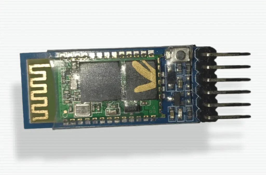
HC-05 Bluetooth Module
Bluetooth is a medium of wireless communication between two or more devices. HC-05 is a very popular Bluetooth module for its low power consumption and reliability. It communicates with Arduino using universal asynchronous receiver-transmitter(UART) protocol. UART is a serial communication that doesn’t need any clock signal that’s why its named as asynchronous receiver-transmitter. We will discuss more about UART in another tutorial. Let’s observe the pin out of HC-05.
Features of HC-05 Module
- Bluetooth 2.0+EDR (Enhanced Data Rate) compliant.
- Supports Master and Slave mode of operation.
- Easy to use serial interface.
- Operating Voltage: 3.3V to 5V DC.
- Operating Current: less than 40mA (at 3.3V).
- Operating frequency: 2.4GHz ISM band.
- Communication range: up to 10 meters (depending on the environment).
- Maximum data rate: 2.1Mbps
- Can be configured using AT commands.
HC-05 Bluetooth Module Pinout
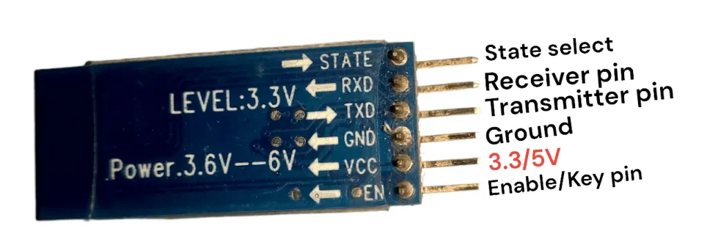
HC-05 module pin description
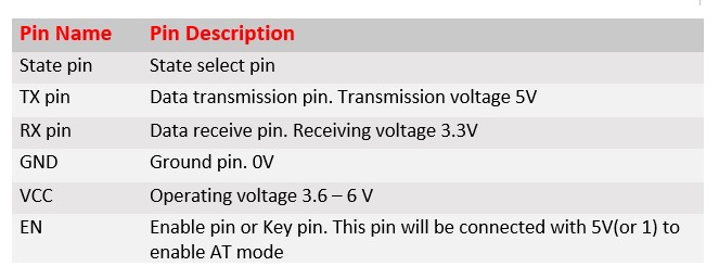
Note: Rx pin receives a 3.3V signal. To do that you can use the voltage divider rule. To simplify our tutorial, we will not use the voltage divider rule but it is recommended to 3.3V otherwise your Rx pin may be damaged.
Now we will configure the HC-05 with the help of AT command.
Configuring HC-05 using AT command
Your HC-05 Bluetooth module may have default name and password. If you want to change name and password of your HC-05 you must configure it with AT commands. AT means Attention. AT Commands are sent to the module serially using a USB-to-TTL cable or an Arduino.
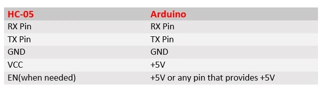
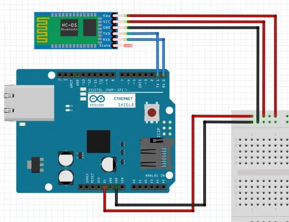
For AT command the interfacing with Arduino RX pin of Arduino must be connected with the Rx pin of HC-05 and Tx pin of Arduino is connected to Tx pin of HC-05. The most important part of AT commend is the enable pin must be connected to +5V supply of the Arduino.
Step 01: Connect your Arduino and HC-05 with following circuit diagram.
Step 02: Open your Arduino IDE and create a new Sketch. For AT command we don’t write code because we just configure our HC-05 module. You just keep default code like this.
void setup() {
  // put your setup code here, to run once:
}
void loop() {
  // put your main code here, to run repeatedly:
}
Step 03: Compile your code and select right Arduino board and port. Then upload your code by pressing upload button of Arduino IDE. Always remember you should disconnect Rx and Tx pin of your Arduino during uploading session. If your Bluetooth module into AT mode then, The LED of HC-05 will NO for 1 to 2 seconds and then OFF for 1 to 2 seconds.
Step 04: Open your serial monitor select baud rate 48400 and select both NL&CL that is shown below.
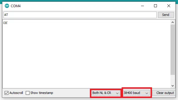
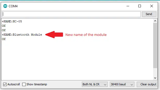
Step 05: Write AT on serial command box. If you see OK, then everything is perfect. If you write AT+NAME? on command box, then the serial monitor will show HC-05(default name of your Bluetooth module). Others commands are shown below.
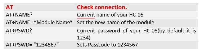
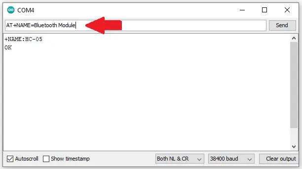
For example, if you write AT+NAME? in the serial monitor of Arduino IDE and press enter, you will see a massage “HC-05” which is default name of HC-05. You can change your module name by AT+NAME=”NAME” command.
We have been configuring our Bluetooth module. Now we will create a project that shows how we can control our Arduino by using a smartphone.
Interfacing HC-05 Bluetooth module with Arduino (The Project)
Hardware requirements
[wptb id=950]
For troubleshooting, some extremely useful test equipment
[wptb id=890]
Affiliate Disclosure: When you click on links to make a purchase, this can result in this website earning a commission. Affiliate programs and affiliations include, but are not limited to Amazon.com
Circuit Schematics
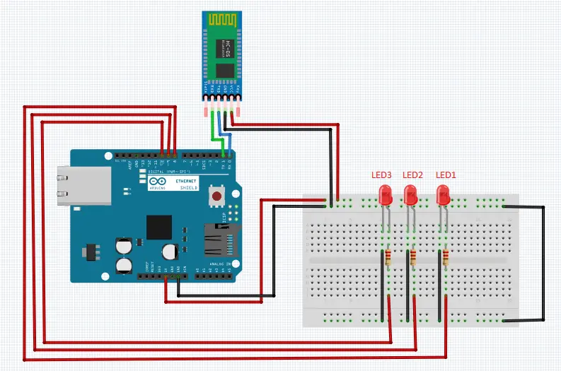
Connection Description

Preparing Bluetooth terminal application
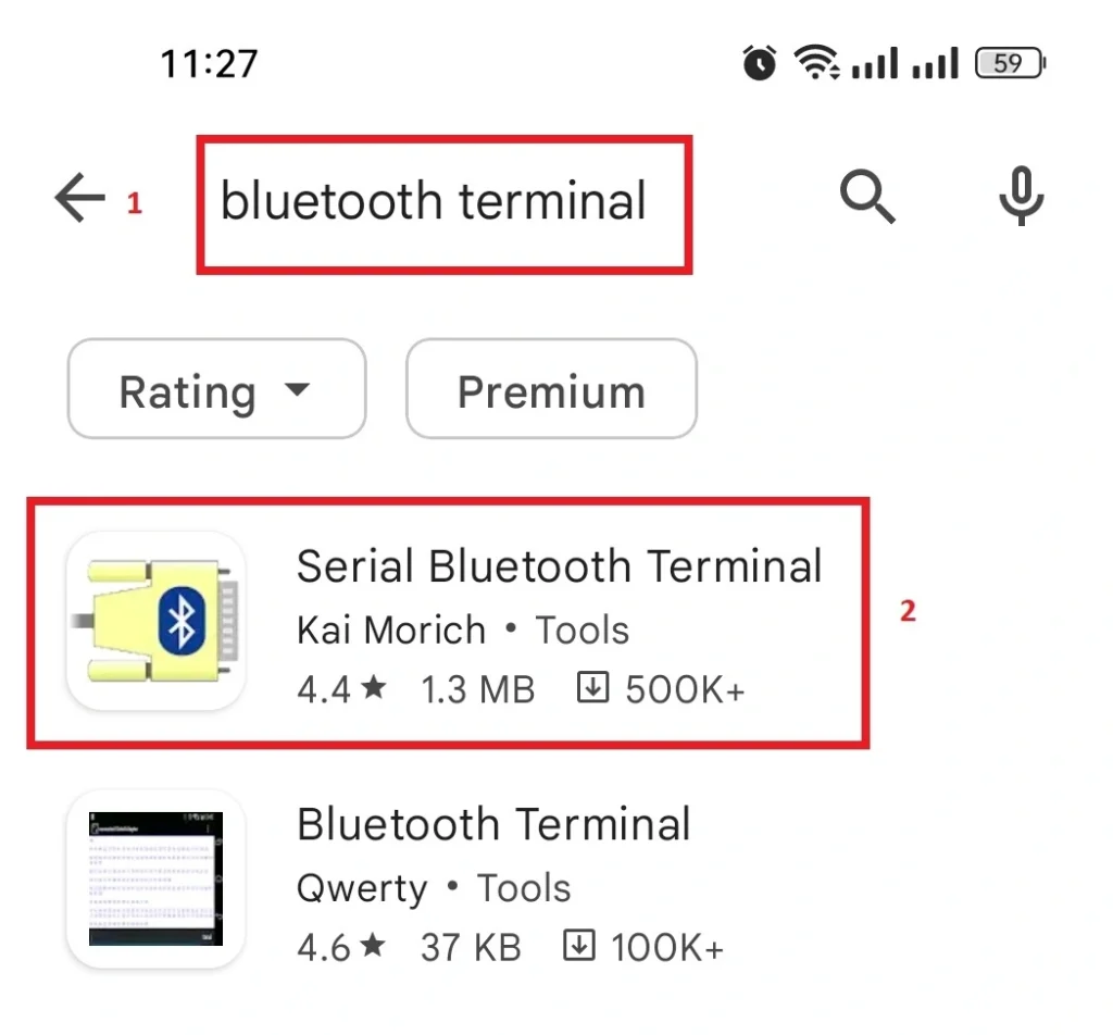
Step 1: Go to the google play store from your Andriod phone and search for “Bluetooth Terminal” select the application shown below and hit install. After install the application open it.
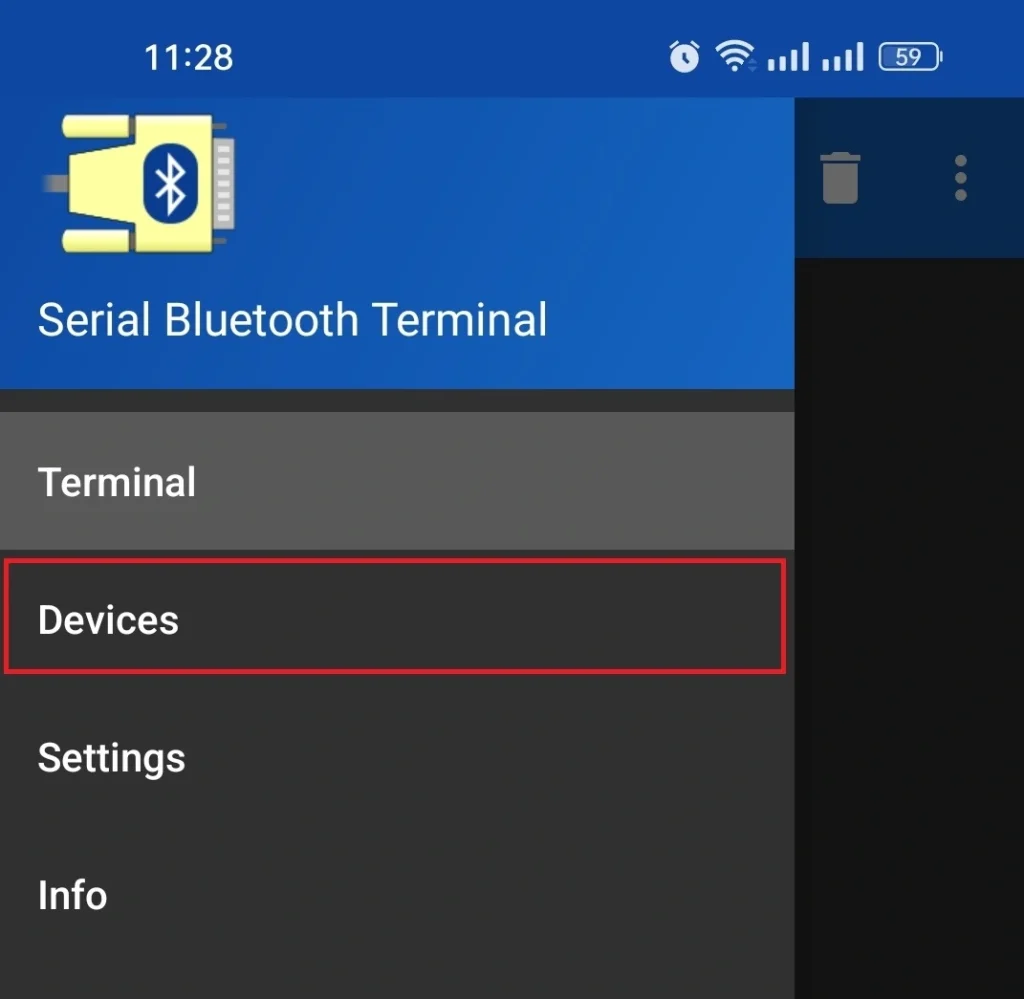
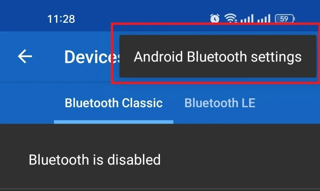
Step 2: Go to the devices option from the application
Step 3: Then select “Andriod Bluetooth Settings”
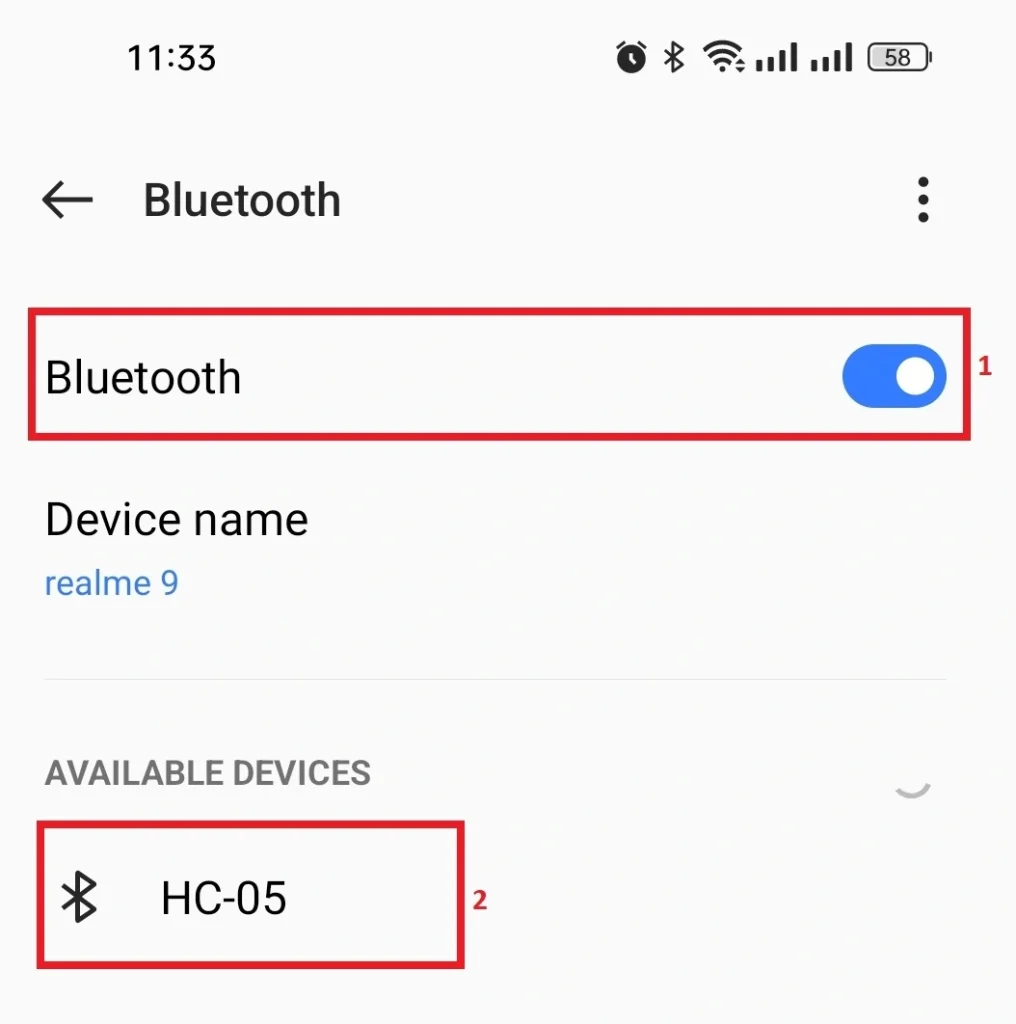
Step 4: Enable your Bluetooth and select HC-05 Bluetooth from the drop-down menu.
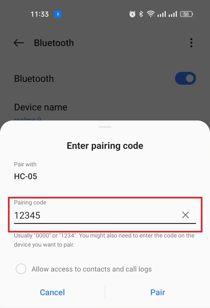
Step 5: Now, Enter the pairing password and click on Pair.
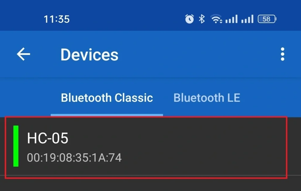
Step 6: Go back to your Serial terminal application and click on devices. You will see that your bluetooth module HC-05 is paired with your smartphone.
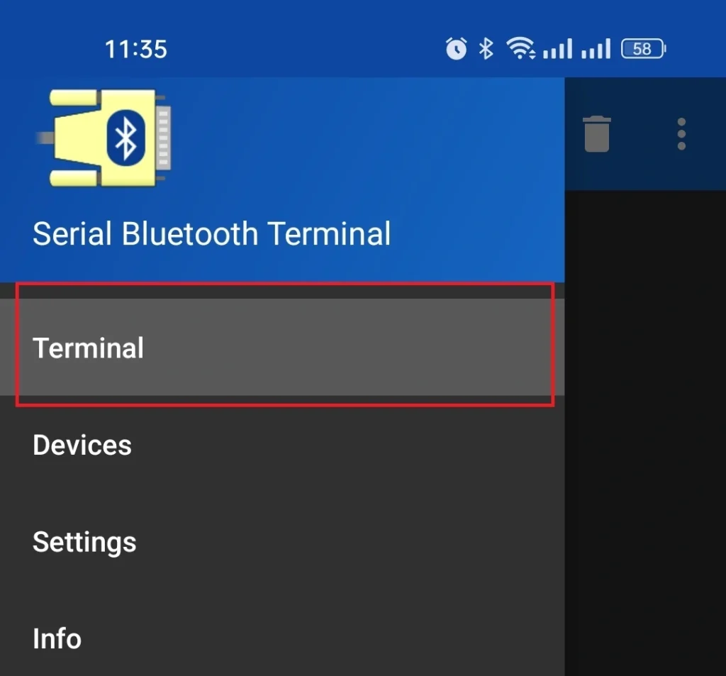
Step 7: Finally click on Terminal of the serial monitor application and start sending commands to your Bluetooth module
Source code and description
We have three LEDs. Our aim is to control three LEDs with our smartphone. When we send 1 by smartphone then LED1 will glow and when sending 2 the LED2 will glow and for sending 3, LED3 will glow.
Code description
At first, we define pin numbers 8,9, and 10 for LED1, LED2, and LED3 respectively.
#define LED_01 8                           //define pin 8 for LED1
#define LED_02 9                           //define pin 9 for LED2
#define LED_03 10                          //define pin 10 for LED3
In setup function set the bund rate 9600 for serial communication. Set pin number 8,9, and 10 as OUTPUT using pinMode().
Serial.begin(9600);                     //set the bund rate 9600
  pinMode(LED_01, OUTPUT);                //take pin 8 as OUTPUT
  pinMode(LED_02, OUTPUT);                //take pin 9 as OUTPUT
  pinMode(LED_03, OUTPUT);                //take pin 10 as OUTPUT
In the loop function availability of data is checked by Serial.available() function. if data is available then it is converted into an integer by Serial.parseInt(). This integer data will store in the input_value variable. Also, sending data will print to the serial monitor.
 if(Serial.available()){                //true when sending data is available
    input_value = Serial.parseInt();     //Serial.parseInt()function take serial data as integer
    Serial.print(input_value);           //print seding data
    Serial.print("\n");
When sending data is equal to 1 then the LED1 is turned ON by digitalWrite() function. if sending data is equal to 2 then LED2 will be glowing and for sending 3 LED3 will glow.
if(input_value==1){                  //true if seding data is 1
      digitalWrite(LED_01,HIGH);         //turn ON LED1
      digitalWrite(LED_02,LOW);
      digitalWrite(LED_03,LOW);
    }
    else if(input_value==2){            //true if seding data is 2
      digitalWrite(LED_01,LOW);
      digitalWrite(LED_02,HIGH);        //turn ON LED2
      digitalWrite(LED_03,LOW);
    }
    else if(input_value==3){            //true if send data is 3
      digitalWrite(LED_01,LOW);
      digitalWrite(LED_02,LOW);
      digitalWrite(LED_03,HIGH);        //turn ON LED3
    }
Full code
#define LED_01 8                           //define pin 8 for LED1
#define LED_02 9                           //define pin 9 for LED2
#define LED_03 10                          //define pin 10 for LED3

int input_value=0;
void setup(){
  Serial.begin(9600);                     //set the bund rate 9600
  pinMode(LED_01, OUTPUT);                //take pin 8 as OUTPUT
  pinMode(LED_02, OUTPUT);                //take pin 9 as OUTPUT
  pinMode(LED_03, OUTPUT);                //take pin 10 as OUTPUT
}

void loop(){
  if(Serial.available()){                //true when sending data is available
    input_value = Serial.parseInt();     //Serial.parseInt()function take serial data as integer
    Serial.print(input_value);           //print seding data
    Serial.print("\n");
    if(input_value==1){                  //true if seding data is 1
      digitalWrite(LED_01,HIGH);         //turn ON LED1
      digitalWrite(LED_02,LOW);
      digitalWrite(LED_03,LOW);
    }
    else if(input_value==2){            //true if seding data is 2
      digitalWrite(LED_01,LOW);
      digitalWrite(LED_02,HIGH);        //turn ON LED2
      digitalWrite(LED_03,LOW);
    }
    else if(input_value==3){            //true if send data is 3
      digitalWrite(LED_01,LOW);
      digitalWrite(LED_02,LOW);
      digitalWrite(LED_03,HIGH);        //turn ON LED3
    }
  }
}