LoRa is a low-power long-range wireless communication protocol. It is very effective in remote areas where WiFi, LAN, and cellular networks are not available. Using LoRa you can receive data up to 10 km. In this tutorial, we will learn how we can interface LoRa with Raspberry Pi Pico, also build a small project using Raspberry Pi Pico, Arduino Uno, and LoRa sx1278 module.
What is LoRa?
LoRa (short for Long Range) is a wireless communication technology designed for long-range communication with low power consumption. It’s often used in Internet of Things (IoT) applications where devices need to communicate over long distances while consuming minimal power.
LoRa operates in unlicensed radio frequency bands, allowing for easy deployment without needing regulatory approval in most regions. It uses spread spectrum modulation techniques to achieve long-range communication and can penetrate obstacles like buildings and vegetation more effectively than traditional wireless technologies like Wi-Fi or Bluetooth.
LoRaWAN (LoRa Wide Area Network) is a protocol built on top of LoRa technology, providing features like secure communication, power management, and support for large-scale networks.
LoRa works with different frequency bands in different regions.
| Europe | 868 MHz |
| North America | 915 MHz |
| Asia | 433 MHz |
If you are interested in learning more about LoRa then read this article below:
Interfacing LoRa with Raspberry Pi Pico: The Project
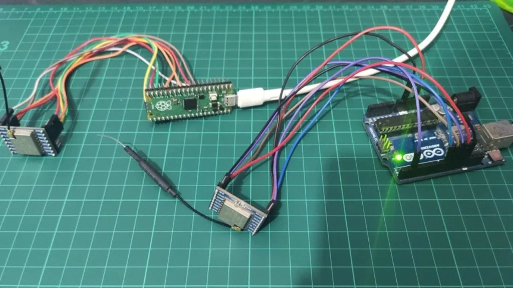
In this project, the Raspberry Pi Pico acts as a sender node and Arduino Uno as a receiver node. We send a message from Raspberry Pi Pico and the Arduino Uno receives this message using LoRa communication. Both the sender (Raspberry Pi Pico) and receiver (Arduino Uno) microcontroller will communicate with LoRa using the SPI communication method. For this project, the code will written in Arduino IDE.
Components list
| Component Name | Quantity | Purchase Link |
|---|---|---|
| Respberry Pi Pico or Pico W | 1 | Amazon | AliExpress |
| LoRa Module | 2 | Amazon | AliExpress |
| Arduino Uno | 1 | Amazon | AliExpress |
| Breadboard | 2 | Amazon | AliExpress |
| Jumper Wire Pack | 1 | Amazon | AliExpress |
| Micro USB Cable | 1 | Amazon | AliExpress |
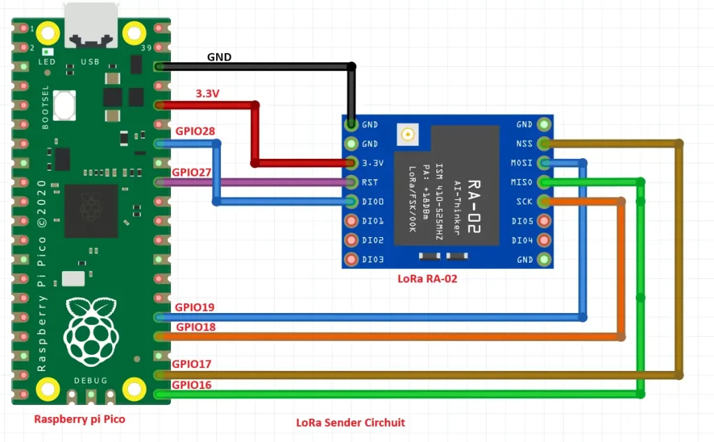
LoRa Sender Circuit
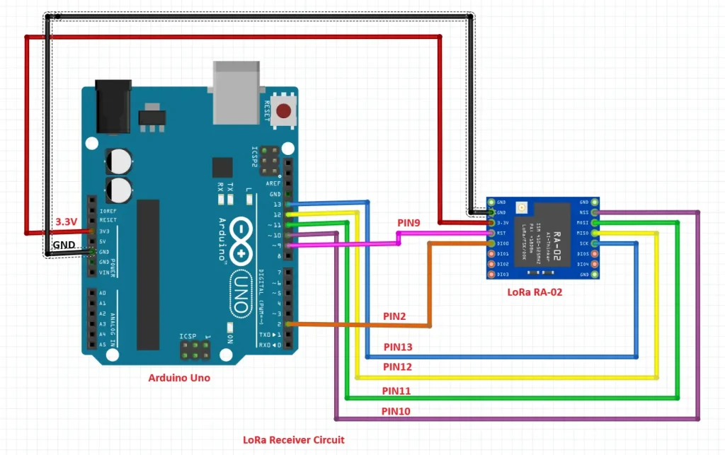
LoRa Receiver Circuit
Preparing Arduino IDE for the project
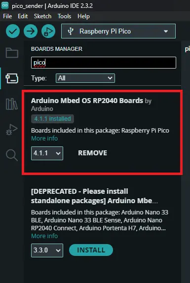
Installing Raspberry Pi Pico Board Manager
Open your Arduino IDE and go to Tools>>Board>>Board manager search for Pico and press enter then install this board manager for Raspberry Pi Pico or Pico W.
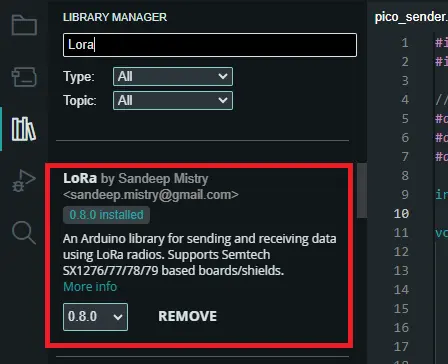
Installing Library
To install LoRa library open your Arduino IDE and go to tools>>manage libraries. In the search box search for Lora and install this library.
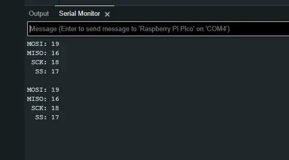
Raspberry Pi Pico SPI Scan
Using the SPI scan code you can easily find the SPI pins of your Raspberry Pi Pico or Pico W. This method saves you time. Open your Arduino IDE create a new sketch copy and paste this code and upload it to your Raspberry Pi Pico.
void setup() {
      Serial.begin(115200);
    }

    void loop() {
      Serial.print("MOSI: ");
      Serial.println(MOSI);
      Serial.print("MISO: ");
      Serial.println(MISO);
      Serial.print(" SCK: ");
      Serial.println(SCK);
      Serial.print("  SS: ");
      Serial.println(SS);
      Serial.println();
      delay(5000);
    }
Then, you can see the SPI pins of your Raspberry Pi Pico in the serial monitor of Arduino IDE. You may have different pins. In this case, your connection between Pico and LoRa module will be different which means according to SPI protocol.
| SPI Pins of Raspberry Pi Pico / Pico W | LoRa Module SPI Pins |
|---|---|
| MOSI | MOSI |
| MISO | MISO |
| SCK | SCK |
| SS | SS |
LoRa Sender Code
#include <SPI.h>
#include <LoRa.h>

//define the pins used by the sender module
#define ss 17
#define rst 27
#define dio0 28

int counter = 0;

void setup() {
  //initialize Serial Monitor
  Serial.begin(115200);
  while (!Serial);
  Serial.println("LoRa Sender");

  //setup LoRa sender module
  LoRa.setPins(ss, rst, dio0);

  //replace the LoRa.begin(---E-) argument with your location's frequency
  //433E6 for Asia
  //866E6 for Europe
  //915E6 for North America
  while (!LoRa.begin(433E6)) {
    Serial.println(".");
    delay(500);
  }
   // Change sync word (0xF3) to match the receiver
  // The sync word assures you don't get LoRa messages from other LoRa transceivers
  // ranges from 0-0xFF
  LoRa.setSyncWord(0xF3);
  Serial.println("LoRa Initializing OK!");
}

void loop() {
  Serial.print("Sending packet: ");
  Serial.println(counter);

  //Send LoRa packet to receiver
  LoRa.beginPacket();
  LoRa.print("EmbeddedThere ");
LoRa.print(counter);
  LoRa.endPacket();

  counter++;

  delay(10000);
}
Code Explanation
#include <SPI.h>
#include <LoRa.h>
In these two lines of code, we include two important libraries: SPI.h for Serial Peripheral Interface communication and LoRa.h for LoRa communication. These libraries provide functions and definitions necessary for interacting with the LoRa transceiver module.
#define ss 17
#define rst 27
#define dio0 28
ss (Slave Select): The pin used for chip select in SPI communication.
rst (Reset): The reset pin for the LoRa module.
dio0 (Digital Input/Output 0): This pin is used for interrupt notifications from the LoRa module.
int counter = 0;
This line declares a global variable counter and initializes it to 0. This variable will be used to keep track of the number of packets sent.
void setup() {
    Serial.begin(115200);
    while (!Serial);
    Serial.println("LoRa Sender");
    LoRa.setPins(ss, rst, dio0);
    while (!LoRa.begin(433E6)) {
        Serial.println(".");
        delay(500);
    }
    LoRa.setSyncWord(0xF3);
    Serial.println("LoRa Initializing OK!");
}
In the setup() function, We initialize serial communication with the Serial Monitor at a baud rate of 115200. We set up the LoRa module by specifying the pins defined earlier and attempting to begin communication with it at a frequency of 433 MHz for Asia. Then, set the sync word to 0xF3 to ensure proper communication between the sender and receiver this must be the same for the receiver also. Finally, we print “LoRa Initializing OK!” to the Serial Monitor.
void loop() {
    Serial.print("Sending packet: ");
    Serial.println(counter);
    LoRa.beginPacket();
    LoRa.print("EmbeddedThere ");
    LoRa.print(counter);
    LoRa.endPacket();
    counter++;
    delay(10000);
}
In the loop() function, We continuously send LoRa packets. Print the current packet number to the Serial Monitor. We begin a LoRa packet, write data (“EmbeddedThere” followed by the packet counter) to the packet, and end the packet. Incrementing the counter variable to keep track of packets sent. Set a 10-second delay before sending the next packet.
LoRa Receiver Code
#include <SPI.h>
#include <LoRa.h>

//define the pins used by the transceiver module
#define ss 10
#define rst 9
#define dio0 2

void setup() {
  //initialize Serial Monitor
  Serial.begin(9600);
  while (!Serial);
  Serial.println("LoRa Receiver");

  //setup LoRa transceiver module
  LoRa.setPins(ss, rst, dio0);

  //replace the LoRa.begin(---E-) argument with your location's frequency
  //433E6 for Asia
  //866E6 for Europe
  //915E6 for North America
  while (!LoRa.begin(433E6)) {
    Serial.println(".");
    delay(500);
  }
   // Change sync word (0xF3) to match the receiver
  // The sync word assures you don't get LoRa messages from other LoRa transceivers
  // ranges from 0-0xFF
  LoRa.setSyncWord(0xF3);
  Serial.println("LoRa Initializing OK!");
}

void loop() {
  // try to parse packet
  int packetSize = LoRa.parsePacket();
  if (packetSize) {
    // received a packet
    Serial.print("Received packet '");

    // read packet
    while (LoRa.available()) {
      String LoRaData = LoRa.readString();
      Serial.print(LoRaData);
    }

    // print RSSI of packet
    Serial.print("' with RSSI ");
    Serial.println(LoRa.packetRssi());
  }
}
Code Explanation
Before the setup function the first few lines are almost the same as the receiver except pin numbers. So, we can skip these lines.
void setup() {
    Serial.begin(9600);
    while (!Serial);
    Serial.println("LoRa Receiver");

    LoRa.setPins(ss, rst, dio0);

    while (!LoRa.begin(433E6)) {
        Serial.println(".");
        delay(500);
    }
    LoRa.setSyncWord(0xF3);
    Serial.println("LoRa Initializing OK!");
}
In the setup() function, Serial communication is initialized with the baud rate set to 9600. We wait for the Serial Monitor to open and then print “LoRa Receiver”. Similar to the sender code, we set the sync word to 0xF3 to ensure proper communication between the sender and receiver. All other lines are the same as the sender code.
void loop() {
    int packetSize = LoRa.parsePacket();
    if (packetSize) {
        Serial.print("Received packet '");
        while (LoRa.available()) {
            String LoRaData = LoRa.readString();
            Serial.print(LoRaData);
        }
        Serial.print("' with RSSI ");
        Serial.println(LoRa.packetRssi());
    }
}
In the loop() function, We attempt to parse a LoRa packet using LoRa.parsePacket().
If a packet is received (packetSize is non-zero), we print “Received packet ‘” to the Serial Monitor.
While data is available from the LoRa module, we read the packet data as a string and print it to the Serial Monitor in my case it was “EmbeddedThere”. We also print the Received Signal Strength Indication (RSSI) of the packet using LoRa.packetRssi() function. LoRa operates RSSI between -30dBm to -150dBm. -30dBm means a very strong signal.
Uploading The Code
Copy and paste the sender code then save the file and hit the upload button to upload the code in your Raspberry Pi Pico or Pico W. If you are new in Arduino IDE and Pico then follow this article.
Also, For the receiver code copy and paste the receiver code and go to Tools>>Board>>Arduino AVR board>>select Arduino Uno. After again go to Tools>>port>>select the right Port(COM1, COM2, COM4,COM5..and so on). And hit the upload button to upload the code to your Arduino Uno.
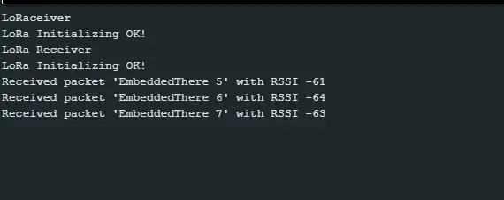
The Result
On the serial monitor, you will see this message(receiver serial terminal).