In this tutorial, we will discuss how we can interface ESP32 (as master) to any RS485 (Modbus RTU) based sensor (as slave) using Arduino IDE. We will create an example project by interfacing a RS485 Modbus protocol based energy meter (DDM18SD) using MAX485 (TTL to RS485) module and collect current, voltage, and frequency data from the energy meter.
Get 50% Off My Embedded Systems Book
Watch a short ad to unlock the special discount link for my book.
You may also like reading:
- RS485 Communication Protocol: Basics, Working Principle & Application
- How to interface STM32 with RS485 (Modbus) sensors
- How to interface Arduino with RS232 communication protocol
- Introduction to RS232 Serial Communication Protocol
- How to interface Modbus RTU (RS485) sensors with Arduino
- How to interface Arduino with RS485 (Modbus) protocol with example code
- Multiple ESP32 Communication via RS485
Our other ESP32-related tutorials are:
- IoT Based Energy Monitoring System using ESP32 and Firebase
- Esp32 LoRa tutorial using Arduino IDE with example code
- ESP32 LoRaWAN Gateway tutorial with Sensor Node
- How to install ESP32 Board in Arduino IDE
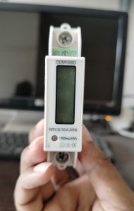
DDM18SD RS485 based Energy meter
The DDM18SD is a type of energy meter, specifically an electronic watt-hour meter used to measure the electric energy consumed by residential or commercial customers. The DDM18SD displays the energy consumption in kilowatt-hours (kWh) and can be read remotely using a handheld device or connected to a data collection system for an automated meter reading. Energy meters like this can play an important role in accurately measuring and billing customers for their electricity consumption.
DDM18SD Energy Meter Features
- Display and reading: current, voltage, frequency, power factor, active power, reactive power, etc
- Automatically detect the flow direction and command of the load current
- One-way measurement of single-phase two-wire active power
- RS485 data communication enabled
- Voltage Specification: 220V
- Frequency: 50Hz
- Communication protocol: MODBUS-RTU, DL/T645-1997, DL/T645-2007
- Screen Display: Multi-function Cycle Display
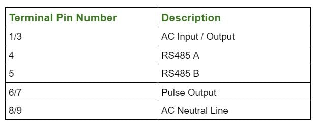
DDM18SD Pinout
The pinout of the DDM18SD energy meter can vary depending on the manufacturer and the specific model. However, in general, most energy meters have several terminal pins that connect the meter to the electrical wiring of the building.
In our case, the DDM18SD pinout is given below
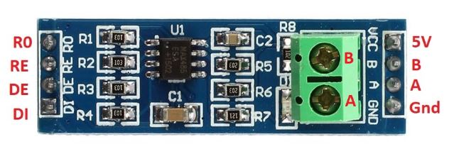
MAX485 – TTL to RS485 converter
The MAX485 is a popular RS-485 transceiver integrated circuit (IC) that allows communication between devices using the RS-485 communication protocol. The MAX485 is designed to convert a standard TTL (Transistor-Transistor Logic) voltage level to the differential voltage levels required by the RS-485 standard, and vice versa.
MAX485 Features
- Supply Voltage: 3.3 to 5.5 V
- Data Rate: Up to 10 Mbps
- Driver Output Voltage: ±7V (min)
- Receiver Input Voltage: ±200 mV (min)
- Driver Output Current: ±120 mA (min)
- Driver Short-Circuit Current Limit: ±500 mA
- Operating Temperature: -40°C to +85°C
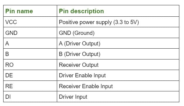
MAX485 Pinout
RS485 serial data communication between esp32 and DDM18SD energy meter (The Project)
In this section of the tutorial, we will first draw the circuit diagram of the rs485 communication between esp32 (as master) and DDM18SD (as a slave sensor). After that, we will code an example project which is to collect the voltage (in Volt), current (in Amps), and frequency (in Hz) data from DDM18SD energy meter vai MAX485 IC to esp32. Then we will show the collected data to Arduino IDE serial monitor
Component List for the Project
| Component Name | Quantity | Purchase Link |
|---|---|---|
| ESP32 development board | 1 | Amazon | AliExpress |
| MAX485 TTL to RS485 converter module | 1 | Amazon | AliExpress |
| Breadboard | 1 | Amazon | AliExpress |
| Jumper Wire pack | 1 | Amazon | AliExpress |
| RS485 based Energy Meter | 1 | Amazon | AliExpress |
For troubleshooting, some extremely useful test equipment
| Equipment Name | Purchase Link |
|---|---|
| Best Oscilloscope for Professionals | Amazon |
| Best Oscilloscope for Beginners | Amazon | AliExpress |
| Logic Analyzer | Amazon | AliExpress |
| Best Budget Multimeter | Amazon | AliExpress |
| Adjustable Bench Power Supply | Amazon | AliExpress |
Affiliate Disclosure: When you click on links to make a purchase, this can result in this website earning a commission.
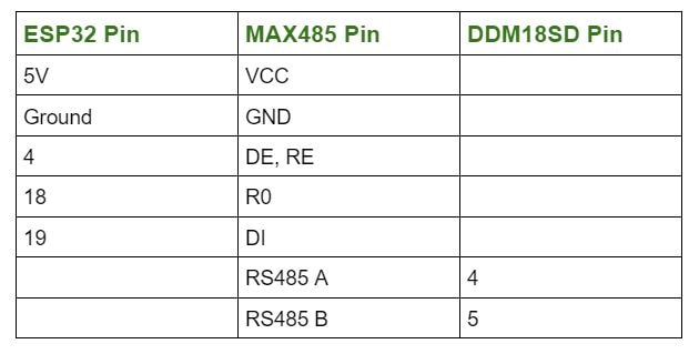
Circuit Connection between ESP32, MAX485 and DDM18SD
Circuit Diagram
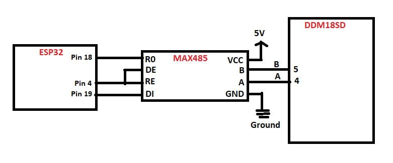
Preparing Arduino IDE
Step 1: Just open your Arduino IDE and go to File > New and open a new file.
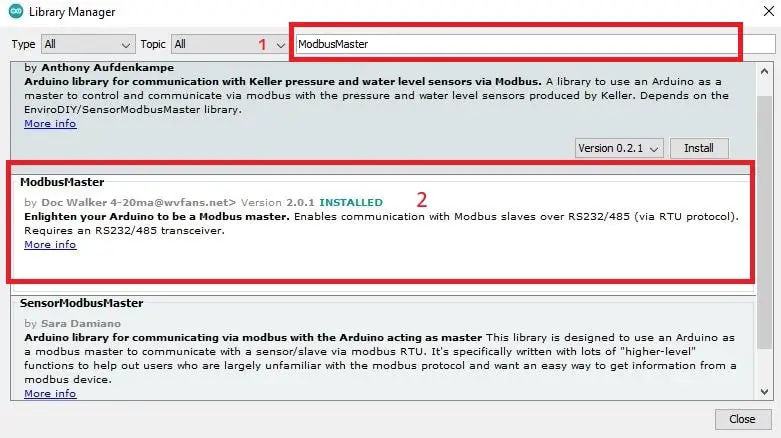
Step 2: Then go to Tools > manage Libraries and search for ModbusMaster by Doc walker in the search bar the hit Install.
Modbus Library Functions
The following Modbus functions are available in this library:
Discrete Coils/Flags functions:
- 0x01 – Read Coils
readCoils(uint16_t u16ReadAddress, uint16_t u16BitQty);
- 0x02 – Read Discrete Inputs
readDiscreteInputs(uint16_t u16ReadAddress, uint16_t u16BitQty);
- 0x05 – Write Single Coil
writeSingleCoil(uint16_t u16WriteAddress, uint8_t u8State);
- 0x0F – Write Multiple Coils
writeMultipleCoils(uint16_t u16WriteAddress, uint16_t u16BitQty);
Registers functions:
- 0x03 – Read Holding Registers
readHoldingRegisters(uint16_t u16ReadAddress, uint16_t u16ReadQty);
- 0x04 – Read Input Registers
readInputRegisters(uint16_t u16ReadAddress, uint8_t u16ReadQty);
- 0x06 – Write Single Register
writeSingleRegister(uint16_t u16WriteAddress, uint16_t u16WriteValue);
- 0x10 – Write Multiple Registers
writeMultipleRegisters(uint16_t u16WriteAddress, uint16_t u16WriteQty);
- 0x16 – Mask Write Register
maskWriteRegister(uint16_t u16WriteAddress, uint16_t u16AndMask, uint16_t u16OrMask);
- 0x17 – Read Write Multiple Registers
readWriteMultipleRegisters(uint16_t u16ReadAddress, uint16_t u16ReadQty, uint16_t u16WriteAddress, uint16_t u16WriteQty);
Please Note: All these functions return 0 on success; exception number on failure. If you want to read more about the library, please visit its GitHub page.
Full Code
.ino file for Arduino IDE
// github link: https://github.com/4-20ma/ModbusMaster
#include <ModbusMaster.h>
/* Modbus stuff */
#define MODBUS_DIR_PIN 4 // connect DR, RE pin of MAX485 to gpio 4
#define MODBUS_RX_PIN 18 // Rx pin
#define MODBUS_TX_PIN 19 // Tx pin
#define MODBUS_SERIAL_BAUD 9600 // Baud rate for esp32 and max485 communication
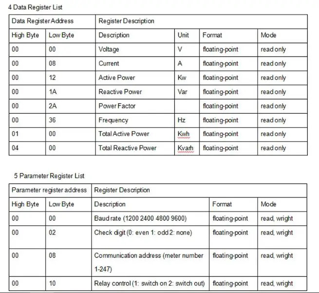
// voltage, current and frequency data register of DDM18SD
uint16_t data_register[3] = {0x0000, 0x0008, 0x002A};
//Initialize the ModbusMaster object as node
ModbusMaster node;
// Pin 4 made high for Modbus transmision mode
void modbusPreTransmission()
{
delay(500);
digitalWrite(MODBUS_DIR_PIN, HIGH);
}
// Pin 4 made low for Modbus receive mode
void modbusPostTransmission()
{
digitalWrite(MODBUS_DIR_PIN, LOW);
delay(500);
}
void setup()
{
// esp serial communication
Serial.begin(115200);
pinMode(MODBUS_DIR_PIN, OUTPUT);
digitalWrite(MODBUS_DIR_PIN, LOW);
//Serial2.begin(baud-rate, protocol, RX pin, TX pin);.
Serial2.begin(MODBUS_SERIAL_BAUD, SERIAL_8E1, MODBUS_RX_PIN, MODBUS_TX_PIN);
Serial2.setTimeout(200);
//modbus slave ID 14
node.begin(14, Serial2);
// callbacks allow us to configure the RS485 transceiver correctly
node.preTransmission(modbusPreTransmission);
node.postTransmission(modbusPostTransmission);
}
void loop()
{
uint8_t result;
uint16_t data[2];
int i;
float reading;
for(i=0; i<=2; i++){
//Modbus function 0x04 Read Input Registers according to energy meter datasheet
result = node.readInputRegisters(data_register[i], 1);
if (result == node.ku8MBSuccess) {
Serial.println("Success, Received data: ");
//Retrieve the data from getResponseBuffer(uint8_t u8Index) function.
//that is return 16-bit data. our energy meter return 32-bit data everytime.
//that's why, we take the value to a array called data
data[0]=node.getResponseBuffer(0x00);
data[1]=node.getResponseBuffer(0x01);
//read voltage
if(data_register[i] == 0x0000){
Serial.print("Volatge: ");
// we just convert the uint16_t type data array to float type using type casting
reading = *((float *)data);
Serial.print(reading);
Serial.println(" Volt");
}
//read current
if(data_register[i] == 0x0008){
Serial.print("Current: ");
// we just convert the uint16_t type data array to float type using type casting
reading = *((float *)data);
Serial.print(reading);
Serial.println(" Amps");
}
//read Frequency
if(data_register[i] == 0x002A){
Serial.print("Frequency: ");
// we just convert the uint16_t type data array to float type using type casting
reading = *((float *)data);
Serial.print(reading);
Serial.println(" Hz");
}
} else {
Serial.print("Failed, Response Code: ");
Serial.print(result, HEX);
Serial.println("");
delay(5000);
}
}
delay(1000);
}
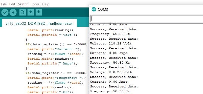
Output of the Code
Output of the code in Arduino IDE serial monitor
DDM18SD energy meter RS485 (Modbus RTU) register reference