
In this tutorial, we will build a complete ESP32 Modbus TCP client using the Wiznet W5500 Ethernet module over SPI. We will also run a Modbus TCP server on a PC and create a simple Web GUI to toggle a register value. Finally, the ESP32 will read that register and turn an LED ON/OFF.
Introduction to Modbus TCP/IP
Modbus TCP/IP is the Ethernet version of Modbus. Instead of serial lines (like RS485), it uses TCP sockets. A Modbus TCP device usually works in one of these roles:
• Client (Master): initiates read/write requests
• Server (Slave): responds and holds registers/coils
In this tutorial:
- PC = Modbus TCP Server (holds register values)
- ESP32 + W5500 = Modbus TCP Client (reads register value)
- LED = Output controlled by register value
Wiznet W5500 Ethernet Module
The W5500 is a hardware TCP/IP Ethernet controller that communicates with microcontrollers through SPI. It is popular for embedded Ethernet projects because it offloads most of the TCP/IP stack processing from the MCU.
W5500 Features
- SPI interface (easy to connect with ESP32)
- Supports TCP, UDP, ICMP, ARP, and more
- Stable wired Ethernet communication for industrial networks
W5500 Important Pins
Most W5500 breakout boards provide these important pins:
- MOSI, MISO, SCLK – SPI communication
- CS – Chip Select
- RST – Reset input
- 3V3, GND – Power (use 3.3V)
ESP32 Modbus TCP over Ethernet (The Project)
In this project, the ESP32 reads a Holding Register from a Modbus TCP server and controls an LED.
Logic:
- Register value = 1 → LED ON
- Register value = 0 → LED OFF
Component List
| Component Name | Quantity | Notes | Purchase Link |
| ESP32 development board | 1 | ESP32 DevKit / ESP32 Dev Module | Amazon | AliExpress |
| Wiznet W5500 Ethernet module | 1 | SPI Ethernet module | Amazon | AliExpress |
| Breadboard | 1 | Amazon | AliExpress | |
| Jumper wire pack | 1 | Amazon | AliExpress | |
| LED + Resistor (220Ω–1kΩ) | 1 | Any 5mm LED is fine | Amazon | AliExpress |
| Ethernet cable | 1 | Connect to PC/router/switch | Amazon | AliExpress |
| USB cable | 1 | For ESP32 power and programming | Amazon | AliExpress |
Affiliate Disclosure: When you click on links to make a purchase, this can result in this website earning a commission.
Circuit Connection between ESP32 and W5500
Connect the W5500 module with ESP32 using VSPI pins.
| W5500 Pin | ESP32 Pin |
| MOSI | GPIO 23 |
| MISO | GPIO 19 |
| SCLK | GPIO 18 |
| CS | GPIO 5 |
| RST | GPIO 4 |
| 3V3 | 3V3 |
| GND | GND |
LED Connection
- LED Anode (+) → GPIO 13 (through resistor)
- LED Cathode (−) → GND
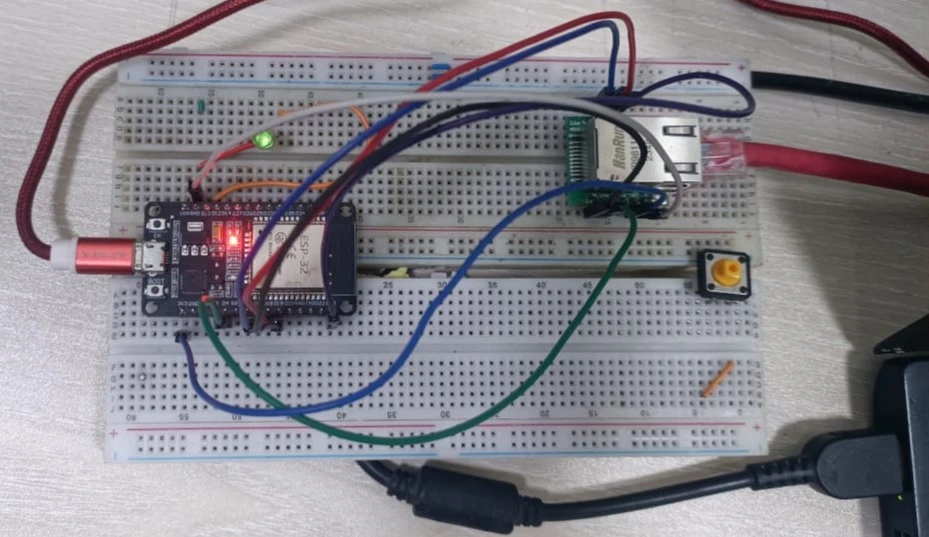
Hardware setup (ESP32 + W5500 on breadboard)
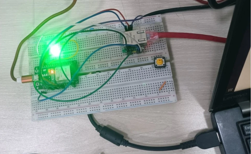
LED ON state (test output)
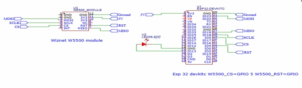
Circuit diagram (schematic)
Network Setup (Static IP)
This project uses a static IP configuration so the ESP32 can always find the PC server.
Example IP configuration:
- PC (Modbus Server): 192.168.10.1
- ESP32 (Ethernet Client): 192.168.10.2
- Subnet: 255.255.255.0
- Gateway: 192.168.10.1 (keep it the same for local testing)
Tip: If you are directly connecting PC ↔ W5500 (without a router), still set a static IP on both sides in the same subnet.
Preparing Arduino IDE
Step 01: Open Arduino IDE and create a new sketch.
Step 02: Go to Sketch → Include Library → Manage Libraries, search for Ethernet and install it.
Step 03: Select your ESP32 board from Tools → Board and choose the correct COM port.
Step 04: Upload the code and open the Serial Monitor at 115200 baud.
Code Explanation
The ESP32 code does four important tasks:
1) Resets and initializes the W5500 module
2) Configures Ethernet with a static IP
3) Connects to the Modbus TCP server using a TCP socket
4) Sends a Modbus TCP Read Holding Register (0x03) request, parses the response, and updates the LED
Key definitions used in this project:
- W5500_CS = GPIO 5
- W5500_RST = GPIO 4
- LED_PIN = GPIO 13
- Modbus server IP = 192.168.10.1
- Modbus port = 1502
Full Code (ESP32 Modbus TCP Client) – Arduino IDE
#include <Arduino.h>
#include <SPI.h>
#include <Ethernet.h>

// ---------- Pin definitions ----------
#define W5500_CS   5
#define W5500_RST  4
#define LED_PIN    13   // LED we want to control

// ---------- Network configuration ----------
byte mac[] = { 0x02, 0x11, 0x22, 0x33, 0x44, 0x55 };

// ESP32 + W5500 static IP
IPAddress ip(192, 168, 10, 2);
IPAddress gateway(192, 168, 10, 1);
IPAddress subnet(255, 255, 255, 0);
IPAddress dns(192, 168, 10, 1);

// Modbus server (your PC)
IPAddress serverIp(192, 168, 10, 1);
const uint16_t MODBUS_PORT = 1502;

EthernetClient client;
uint16_t transactionId = 1;
bool ledState = false;

// ---------- Helpers ----------
void resetW5500() {
  pinMode(W5500_RST, OUTPUT);
  digitalWrite(W5500_RST, LOW);
  delay(10);
  digitalWrite(W5500_RST, HIGH);
  delay(200);
}

void printNetworkInfo() {
  Serial.print("IP address:   ");
  Serial.println(Ethernet.localIP());
  Serial.print("Subnet mask:  ");
  Serial.println(Ethernet.subnetMask());
  Serial.print("Gateway:      ");
  Serial.println(Ethernet.gatewayIP());
}

bool ensureConnected() {
  if (client.connected()) return true;

  Serial.println("[Modbus] Connecting to server...");
  if (!client.connect(serverIp, MODBUS_PORT)) {
    Serial.println("[Modbus] Connection failed.");
    return false;
  }
  Serial.println("[Modbus] Connected.");
  return true;
}

// Read Holding Register (FC 0x03), quantity=1
bool modbusReadSingleRegister(uint8_t unitId,
                              uint16_t regAddr,
                              uint16_t &outValue) {
  if (!ensureConnected()) return false;

  uint8_t frame[12];
  uint16_t tid = transactionId++;

  // MBAP header (7 bytes)
  frame[0] = (tid >> 8) & 0xFF;
  frame[1] = tid & 0xFF;
  frame[2] = 0x00;
  frame[3] = 0x00;
  frame[4] = 0x00;
  frame[5] = 0x06;     // UnitId + PDU length
  frame[6] = unitId;   // Unit ID

  // PDU
  frame[7]  = 0x03;    // Read Holding Registers
  frame[8]  = (regAddr >> 8) & 0xFF;
  frame[9]  = regAddr & 0xFF;
  frame[10] = 0x00;
  frame[11] = 0x01;    // read 1 register

  if (client.write(frame, sizeof(frame)) != sizeof(frame)) {
    Serial.println("[Modbus] TCP write failed (read).");
    client.stop();
    return false;
  }

  // Expected response: 7 (MBAP) + 1 (FC) + 1 (byte count) + 2 (data) = 11 bytes
  const size_t expected = 11;
  uint32_t start = millis();
  while (client.available() < (int)expected && (millis() - start) < 1000) {
    delay(1);
  }

  if (client.available() < (int)expected) {
    Serial.println("[Modbus] Response timeout (read).");
    client.stop();
    return false;
  }

  uint8_t resp[expected];
  client.read(resp, expected);

  uint8_t fc = resp[7];
  if (fc != 0x03) return false;

  uint8_t byteCount = resp[8];
  if (byteCount != 2) return false;

  outValue = (resp[9] << 8) | resp[10];
  return true;
}

void applyLed(bool on) {
  ledState = on;
  digitalWrite(LED_PIN, ledState ? HIGH : LOW);
  Serial.print("[LED] New state: ");
  Serial.println(ledState ? "ON" : "OFF");
}

void setup() {
  Serial.begin(115200);
  delay(1000);

  Serial.println();
  Serial.println("Booting Modbus TCP LED client...");

  pinMode(LED_PIN, OUTPUT);
  applyLed(false);

  resetW5500();

  // VSPI pins: SCK=18, MISO=19, MOSI=23, SS=W5500_CS
  SPI.begin(18, 19, 23, W5500_CS);
  Ethernet.init(W5500_CS);

  Serial.println("Calling Ethernet.begin(...)");
  Ethernet.begin(mac, ip, dns, gateway, subnet);

  printNetworkInfo();
}

void loop() {
  uint16_t ledCmd = 0;
  bool ok = modbusReadSingleRegister(1, 0, ledCmd); // UnitId=1, HR[0]

  if (ok) {
    bool desired = (ledCmd != 0);
    if (desired != ledState) {
      applyLed(desired);
    } else {
      Serial.print("[LED] State unchanged, command=");
      Serial.println(ledCmd);
    }
  } else {
    Serial.println("[App] Read failed, will retry.");
  }

  delay(500);
}
Python Modbus TCP Server
Now we will run a Modbus server on the PC so that the ESP32 can read holding registers.
Install required libraries:
pip install pymodbus
Modbus Server Code (Modbus_server.py)
Important: In this tutorial, we use port 1502 so it works without admin/root permission. If you want to use the default Modbus port 502, change the port in both client and server.
from pymodbus.server import StartTcpServer
from pymodbus.datastore import ModbusServerContext, ModbusSlaveContext
from pymodbus.datastore import ModbusSequentialDataBlock
from pymodbus.device import ModbusDeviceIdentification
import logging

logging.basicConfig()
log = logging.getLogger()
log.setLevel(logging.INFO)

# Holding registers: start=0, size=100, init all 0
store = ModbusSlaveContext(
   hr=ModbusSequentialDataBlock(0, [0]*100)
)
context = ModbusServerContext(slaves=store, single=True)

identity = ModbusDeviceIdentification()
identity.VendorName  = 'EmbeddedThere'
identity.ProductCode = 'ESP32-W5500'
identity.ProductName = 'Modbus TCP Test Server'
identity.MajorMinorRevision = '1.0'

if __name__ == "__main__":
   StartTcpServer(
       context,
       identity=identity,
       address=("192.168.10.1", 1502)
   )
Run the server:
python3 Modbus_server.py
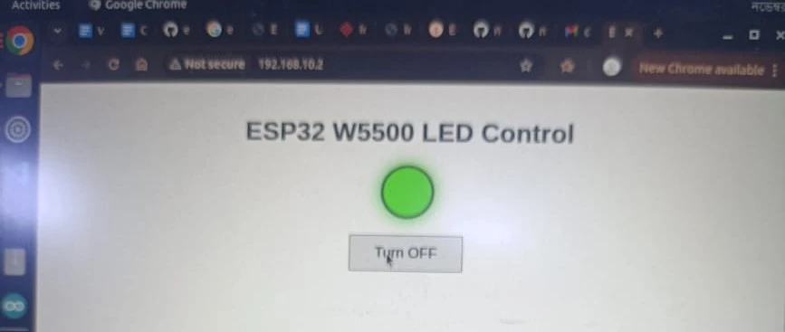
Web GUI to Toggle Modbus Register
This step is optional but very useful. Here, we build a small webpage that can write 0/1 to the holding register (HR[0]).
Install Flask and the PyModbus client:
pip install flask pymodbus
Web GUI Code (Web_gui.py)
from flask import Flask, jsonify
from pymodbus.client import ModbusTcpClient

SERVER_IP = "192.168.10.1"   # Modbus server (PC)
PORT      = 1502
UNIT_ID   = 1

app = Flask(__name__)

def read_led_reg():
    client = ModbusTcpClient(SERVER_IP, port=PORT)
    if not client.connect():
        client.close()
        return 0
    rr = client.read_holding_registers(0, 1, unit=UNIT_ID)
    client.close()
    if rr.isError():
        return 0
    return rr.registers[0]

def write_led_reg(on: bool):
    value = 1 if on else 0
    client = ModbusTcpClient(SERVER_IP, port=PORT)
    if not client.connect():
        client.close()
        return False
    rq = client.write_register(0, value, unit=UNIT_ID)
    client.close()
    return not rq.isError()

@app.route("/")
def index():
    return """
<!DOCTYPE html>
<html>
<head>
<meta charset="utf-8">
<title>ESP32 W5500 LED Control</title>
<style>
body{font-family:sans-serif;text-align:center;margin-top:40px;}
.led{width:60px;height:60px;border-radius:50%;margin:20px auto;border:3px solid #555;background:#444;}
.led.on{background:#0f0;box-shadow:0 0 20px #0f0;}
.btn{padding:10px 30px;font-size:18px;}
</style>
</head>
<body>
 <h1>ESP32 W5500 LED Control</h1>
 <div id="led" class="led"></div>
 <button id="btn" class="btn">Loading...</button>

<script>
async function refreshState(){
 const r  = await fetch('/api/state');
 const js = await r.json();
 const led = document.getElementById('led');
 const btn = document.getElementById('btn');

 if(js.state === 'ON'){
   led.classList.add('on');
   btn.textContent = 'Turn OFF';
 } else {
   led.classList.remove('on');
   btn.textContent = 'Turn ON';
 }
}

async function toggle(){
 await fetch('/api/toggle', {method: 'POST'});
 await refreshState();
}

document.getElementById('btn').addEventListener('click', toggle);
refreshState();
setInterval(refreshState, 2000);
</script>
</body>
</html>
"""

@app.route("/api/state")
def api_state():
    val = read_led_reg()
    return jsonify({"state": "ON" if val != 0 else "OFF", "value": val})

@app.route("/api/toggle", methods=["POST"])
def api_toggle():
    current = read_led_reg()
    desired = (current == 0)
    ok = write_led_reg(desired)
    return jsonify({"ok": ok, "state": "ON" if desired and ok else "OFF" if ok else "ERROR"})

if __name__ == "__main__":
    app.run(host="0.0.0.0", port=5000, debug=True)
Run the Web GUI:
python3 Web_gui.py
Open the page from your browser:
http://192.168.10.1:5000
Result
If everything is correct:
- ESP32 will connect to Ethernet (W5500)
- ESP32 will connect to the Modbus server
- Web GUI will toggle the holding register value
- ESP32 will read the register, and the LED will turn ON/OFF
Troubleshooting
- ESP32 cannot connect: Check Ethernet cable, link LEDs, and confirm your PC IP is 192.168.10.1.
- Timeout/no response: Check MOSI/MISO/SCLK wiring and CS pin number.
- Wrong port: Make sure both the ESP32 and the Python server use the same port (1502 in this tutorial).
- Firewall issue: Allow ports 1502 and 5000 (or disable firewall temporarily for testing).
- LED not changing: Confirm LED polarity and that the LED is connected to GPIO 13 through a resistor.
Conclusion
In this tutorial, we built an ESP32 Modbus TCP client over Ethernet using the W5500 module. We also created a Modbus TCP server on a PC and an optional Web GUI to change holding register values. This structure is a solid starting point for industrial Ethernet sensor nodes, remote relay controllers, and Modbus TCP gateways.
You may also like reading: