
In this tutorial, we will show how to configure and use PIC Microcontroller timer. For this tutorial we will use PIC18F4550 microcontroller for demonstration and also create a simple LED blink project by the help of the PIC timer. So, without further delay, Let’s start.
Our other PIC Microcontroller related tutorials are:
- How to interface PIC Microcontroller with I2C sensors
- How to generate PWM signal using PIC Microcontroller
- Password based Door Lock System using PIC16F, PIC18F Microcontroller
What is Timer?
Timer obviously related to time but in a different way. The primary purpose of using a timer is to create a particular delay. The delay is created by the counting of ticks that come from the microcontroller clock pluses.
Basic principle of Timer
Clock pulses are generated by an external or internal oscillator which can produce 20000000 pulses per second (20Mhz). These oscillators also can be 4Mhz, 10Mhz, 16Mhz so on. Now to create a delay we need to count these pluses and the timer interrupt overflow flag does this task. The flag will be high when pluses reach a particular delay and by measuring that delay with the help of a count variable we produce our desired delay.
PIC 18F4550 Microcontroller Timer
PIC 18F4550 has four timer and they are:
- TIMER0 (8 & 16 bits)
- TIMER1 (16 bits)
- TIMER2 (8 bits)
- TIMER3 (16 bits)
In this article, we will only discuss TIMER0 (8 bits). Before we move into TIMER0 let’s introduce the word Prescaler. Prescaler means how many pulses are required to increment the timer by 1. For 8 bit timer, the range of Prescaler is 1 to 256. If the Prescaler is 32 then it means after every 32 pulses the timer should be incremented by 1.
TIMER0 of PIC 18F4550
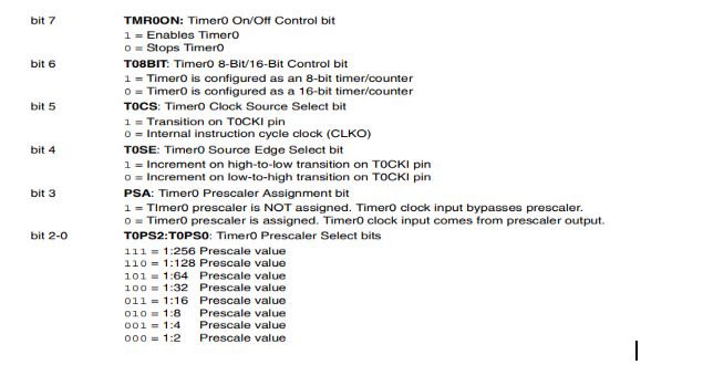
At first we need to configure the timer0 control register whose name is T0CON.
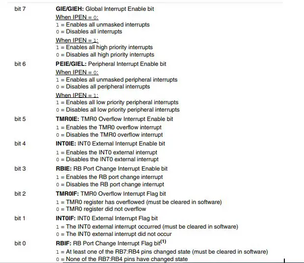
Now, configure the interrupt control resister INTCON. We may not configure all the bits of INTCON.
Key features of TIMER0
- 8 bits and 16bits timer counter operation.
- Readable and writable registers
- 8 bits prescaler (1 – 256)
- Edge select for external clock
- Interrupt on overflow
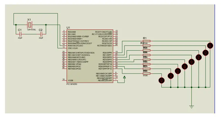
Circuit diagram
For troubleshooting, some extremely useful test equipment
[wptb id=890]
Code explanation
Our aim is to blink 8 LED one by one with the delay of 2 second that means the first LED will glow for 2 second after that the 2nd LED will be also glow for 2 second and so on. After glowing 8 no LED reverse operation will happen i.e. 8 no LED for 2 second 7 no LED for 2 second and so on.
The first few lines are used to configure bits of PIC 18F4550. We take 20MHz external oscillator.
void __interrupt() timer_isr(void) //Interrupt function for timer0
{
if(TMR0IF==1) //Timer interrupt flag is ON due to timer overflow
    {
TMR0 = 100;     //For 1:32 prescal
TMR0IF = 0;       // Clear timer interrupt flag
count++;
    }
}
In the interrupt function count will interment with the input value of the delay function. If the timer is overflow, then timer interrupt flag will be high and count is incremented by 1. Every increment of count value is equivalent of 1ms. So, if delay_ms is 2000 then count value is also 2000. Also, we need to clean interrupt flag.
void delay(int delay_ms){   //Delay function for input delay
    count = 0;
    while(count <= delay_ms); // Loop will be execute until count reached to delay_ms
}
After entering delay_ms microcontroller will wait some time that comes from delay_ms. For example, if delay_ms = 2000 then the interrupt function will start counting the value of ms by incrementing count value. When the count value is equal to ms_delay value then a delay of 2 seconds will be created.
/*****Port Configuration for Timer ******/
    T0CON = 0b11000100;  // Timer0 is ON
    TMR0=100;       // Load the time value for 0.0019968s; delayValue can be between 0-256 only
    TMR0IE=1;       //Enable timer interrupt bit in PIE1 register
    GIE=1;          //Enable Global Interrupt
    PEIE=1;         //Enable the Peripheral Interrupt
    /*****Port Configuration for I/O ******/
    TRISD = 0x00; //Instruct the MCU that all pins on PORT D are output
    PORTD=0x00; //Initialize all pins to 0
In the main function, we need to configure the T0CON register, enable timer0 by bit 7 high(bit7=1), and select 8bit timer by bit 6(bit6=1). Bits 2-0 are prescler select bits. We take 1:32 prescler therefore, 100 will be the value of the bit. For 1ms delay in interrupt function, we need 156 ticks or pulse but if we select 8-bit timer then what about the rest of 100 pules? For this issue TMR0 comes. The value of TMR0 calculating by this formula :
TMR0=256-(delay*FOSC) / (Prescalar*4)
Enable global, peripheral interrupt. Port D is used as output and initialize all pins to 0.
 int flag = 0;
    while(1)
    {
        PORTD = 0b00000001<<a;
        delay(2000);
        if(a<=8 && flag == 0){
         a++;
         if(a == 8){
             flag = 1;
         }
        }
        if(a>=0 && flag == 1){
            a--;
            if(a == 0){
             flag = 0;
         }
        }
    }
}
It is easy to understand that fist LED will glow for 2 seconds and according to condition, a will be incremented by 1. Because of incrementing port D will sift 1 bit left and the 2nd LED will glow for 2 seconds and so on. But after glowing 8 number LED they should glow reverse operation. Therefore, if a=8 then the flag will be high and decrementing the value of a. This operation will continue until the value of a and flag are back to 0.
Full Code
// Configuration Bit Settings for pic18f4550

// CONFIG1L
#pragma config PLLDIV = 1       // PLL Prescaler Selection bits (No prescale (4 MHz oscillator input drives PLL directly))
#pragma config CPUDIV = OSC1_PLL2// System Clock Postscaler Selection bits ([Primary Oscillator Src: /1][96 MHz PLL Src: /2])
#pragma config USBDIV = 1       // USB Clock Selection bit (used in Full-Speed USB mode only; UCFG:FSEN = 1) (USB clock source comes directly from the primary oscillator block with no postscale)

// CONFIG1H
#pragma config FOSC = HS        // Oscillator Selection bits (HS oscillator (HS))
#pragma config FCMEN = OFF      // Fail-Safe Clock Monitor Enable bit (Fail-Safe Clock Monitor disabled)
#pragma config IESO = OFF       // Internal/External Oscillator Switchover bit (Oscillator Switchover mode disabled)

// CONFIG2L
#pragma config PWRT = ON        // Power-up Timer Enable bit (PWRT enabled)
#pragma config BOR = ON         // Brown-out Reset Enable bits (Brown-out Reset enabled in hardware only (SBOREN is disabled))
#pragma config BORV = 3         // Brown-out Reset Voltage bits (Minimum setting 2.05V)
#pragma config VREGEN = OFF     // USB Voltage Regulator Enable bit (USB voltage regulator disabled)

// CONFIG2H
#pragma config WDT = OFF        // Watchdog Timer Enable bit (WDT disabled (control is placed on the SWDTEN bit))
#pragma config WDTPS = 32768    // Watchdog Timer Postscale Select bits (1:32768)

// CONFIG3H
#pragma config CCP2MX = OFF     // CCP2 MUX bit (CCP2 input/output is multiplexed with RB3)
#pragma config PBADEN = OFF     // PORTB A/D Enable bit (PORTB<4:0> pins are configured as digital I/O on Reset)
#pragma config LPT1OSC = OFF    // Low-Power Timer 1 Oscillator Enable bit (Timer1 configured for higher power operation)
#pragma config MCLRE = OFF      // MCLR Pin Enable bit (RE3 input pin enabled; MCLR pin disabled)

// CONFIG4L
#pragma config STVREN = OFF     // Stack Full/Underflow Reset Enable bit (Stack full/underflow will not cause Reset)
#pragma config LVP = OFF        // Single-Supply ICSP Enable bit (Single-Supply ICSP disabled)
#pragma config ICPRT = OFF      // Dedicated In-Circuit Debug/Programming Port (ICPORT) Enable bit (ICPORT disabled)
#pragma config XINST = OFF      // Extended Instruction Set Enable bit (Instruction set extension and Indexed Addressing mode disabled (Legacy mode))

// CONFIG5L
#pragma config CP0 = OFF        // Code Protection bit (Block 0 (000800-001FFFh) is not code-protected)
#pragma config CP1 = OFF        // Code Protection bit (Block 1 (002000-003FFFh) is not code-protected)
#pragma config CP2 = OFF        // Code Protection bit (Block 2 (004000-005FFFh) is not code-protected)
#pragma config CP3 = OFF        // Code Protection bit (Block 3 (006000-007FFFh) is not code-protected)

// CONFIG5H
#pragma config CPB = OFF        // Boot Block Code Protection bit (Boot block (000000-0007FFh) is not code-protected)
#pragma config CPD = OFF        // Data EEPROM Code Protection bit (Data EEPROM is not code-protected)

// CONFIG6L
#pragma config WRT0 = OFF       // Write Protection bit (Block 0 (000800-001FFFh) is not write-protected)
#pragma config WRT1 = OFF       // Write Protection bit (Block 1 (002000-003FFFh) is not write-protected)
#pragma config WRT2 = OFF       // Write Protection bit (Block 2 (004000-005FFFh) is not write-protected)
#pragma config WRT3 = OFF       // Write Protection bit (Block 3 (006000-007FFFh) is not write-protected)

// CONFIG6H
#pragma config WRTC = OFF       // Configuration Register Write Protection bit (Configuration registers (300000-3000FFh) are not write-protected)
#pragma config WRTB = OFF       // Boot Block Write Protection bit (Boot block (000000-0007FFh) is not write-protected)
#pragma config WRTD = OFF       // Data EEPROM Write Protection bit (Data EEPROM is not write-protected)

// CONFIG7L
#pragma config EBTR0 = OFF      // Table Read Protection bit (Block 0 (000800-001FFFh) is not protected from table reads executed in other blocks)
#pragma config EBTR1 = OFF      // Table Read Protection bit (Block 1 (002000-003FFFh) is not protected from table reads executed in other blocks)
#pragma config EBTR2 = OFF      // Table Read Protection bit (Block 2 (004000-005FFFh) is not protected from table reads executed in other blocks)
#pragma config EBTR3 = OFF      // Table Read Protection bit (Block 3 (006000-007FFFh) is not protected from table reads executed in other blocks)

// CONFIG7H
#pragma config EBTRB = OFF      // Boot Block Table Read Protection bit (Boot block (000000-0007FFh) is not protected from table reads executed in other blocks)

// #pragma config statements should precede project file includes.
// Use project enums instead of #define for ON and OFF.

#include <xc.h>
#define _XTAL_FREQ 20000000

int count = 0;
char flag =0;
char i=0;
int a = 0;
int b = 7;

void __interrupt() timer_isr(void) //Interrupt function for timer0

{
    if(TMR0IF==1) //Timer interrupt flag is ON due to timer overflow

    {
        TMR0 = 100;     //For 1:32 prescal
        TMR0IF = 0;     // Clear timer interrupt flag
        count++;

    }

}


void delay(int delay_ms){   //Delay function for input delay
    count = 0;
    while(count <= delay_ms); // Loop will be execute until count reached to delay_ms
}
void main()

{

/*Port Configuration for Timer */

    T0CON = 0b11000100;  // Timer0 is ON
    TMR0=100;       // For 1ms; TMR0 can be between 0-256 only
    TMR0IE=1;       //Enable timer interrupt bit in PIE1 register
    GIE=1;          //Enable Global Interrupt
    PEIE=1;         //Enable the Peripheral Interrupt

    /*Port Configuration for I/O */
    TRISD = 0x00; //All pins on PORT D are output
    PORTD=0x00; //Initialize all pins to 0

    int flag = 0;
    while(1)

    {
        PORTD = 0b00000001<<a; //Left sift of port D
        delay(2000);           // Every LED will glow for 2 sec.
        if(a<=7 && flag == 0){ //Forward operation of 8 LEDs
         a++;
         if(a == 8){
             flag = 1;        //when a = 1 then flag will be high
         }
        }

        if(a>=0 && flag == 1){ //reverse operation of 8 LEDs
            a--;
            if(a == 0){
             flag = 0;       // //After glowing 8 No LED in reverse operation flag back to 0
         }
        }
    }
}