
In this tutorial, we will explain how to generate PWM signal and PWM duty cycle using PIC18F4550 microcontroller with an example in MPLAB X IDE. So that you can able to generate any kind of PWM signal using PIC12F, PIC16F or PIC18F series microcontrollers.
Our other PIC Microcontroller related tutorials are:
- How to interface PIC Microcontroller with I2C sensors
- Password based Door Lock System
- PIC Microcontroller Timer with example code
Basic concepts of Pulse Width Modulation(PWM)
Pulse Width Modulation(PWM) is a digital unipolar square wave signal where the duration of ON and OFF time can be produced by microcontrollers or electronics devises.
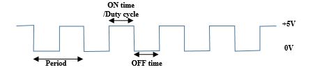
The formula of duty cycle is,

For example, If duty cycle of a signal is 20% with period 100 millisecond then the duration of duty cycle will be 20 millisecond that means the signal will ON of 20 millisecond.
Where we can use the PWM signal?
PWM (Pulse Width Modulation) signals find various applications in different fields due to their versatility and ability to control the average voltage or current. Here are some common applications of PWM signals:
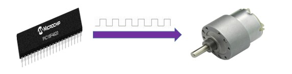
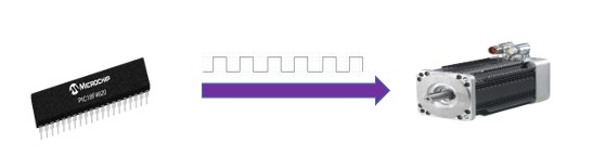
Motor speed control: PWM is extensively used in motor control applications to regulate the speed of motors. By adjusting the duty cycle of the PWM signal, the average voltage or current supplied to the motor can be controlled, resulting in precise speed control. This is crucial in applications such as robotics, industrial automation, and electric vehicles.
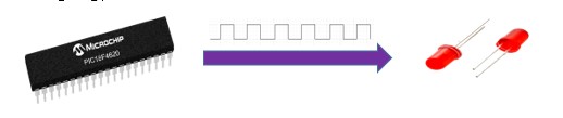
LED dimming: PWM is widely employed for controlling the brightness of LEDs. By varying the duty cycle of the PWM signal, the average current flowing through the LED can be adjusted, allowing for smooth and efficient dimming. LED dimming is utilized in lighting systems, display backlighting, and decorative lighting.
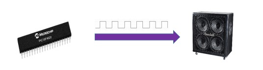
Audio amplification: PWM signals can be used in audio amplification systems, where they act as the basis for Class D amplifiers. PWM allows efficient amplification of audio signals by switching the output transistors rapidly between fully on and fully off states, reproducing the input audio waveform accurately.
Power supply regulation: PWM is utilized in switch-mode power supplies (SMPS) to regulate the output voltage or current. By switching power transistors on and off at a high frequency using PWM, SMPS efficiently convert and regulate electrical power, resulting in smaller size, lighter weight, and improved energy efficiency compared to linear power supplies.
Servo motor control: PWM signals are commonly used to control servo motors in applications such as robotics, RC (Radio Control) vehicles, and automated systems. By varying the duty cycle within a specific range, the servo motor can be positioned at different angles, allowing for precise control over movement.
Battery charging: PWM is employed in battery charging systems to efficiently charge batteries while preventing overcharging. By controlling the duty cycle, the average charging current can be regulated, ensuring the battery is charged effectively without damaging it.
PWM of PIC18F4550 Microcontroller
If we look at the pin diagram of PIC18F4550 then we will find 2 dedicated pins for generating PWM. One pin is marked with C2 and another one is C1.
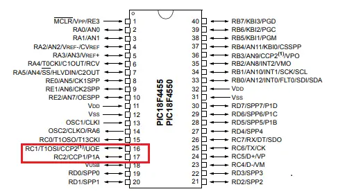
PIC18F4550 has a 10-bit PMW module whose name is the CCP module. PIC18F4550 has two PWM pins which means you can generate 2 PWM at a time.
To properly configure the CCP module for PWM operation, it is important to follow the subsequent steps:
Step 01: Select the microcontroller clock frequency. In our project, we select an 8MHz internal frequency by writing OSCCON=0x72 to the OSCCON register.
Step 02: Set the RC1 or RC2 as the output. In our project, we want to generate a PWM signal to RC2. Therefore, we write TRISCbits.TRISC2=0.
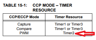
Step 03: For getting PWM output from RC2 we need to configure the CCP1 control register and for RC1 it will be CCP2. Another important thing is to generate the PWM module we must enable TIMER2 for PIC 18F450 microcontroller.
The register PR2 is allocated for PWM period. The formula of calculating PR2 is,

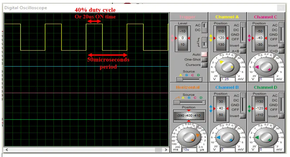
Suppose we need to generate a PWM signal with 20 KHz. That means the period is (1/20000) 50 microsecond. Let consider the internal clock frequency is Fosc = 8MHz and pre-scalar is 1 then, the value of PR2 is,

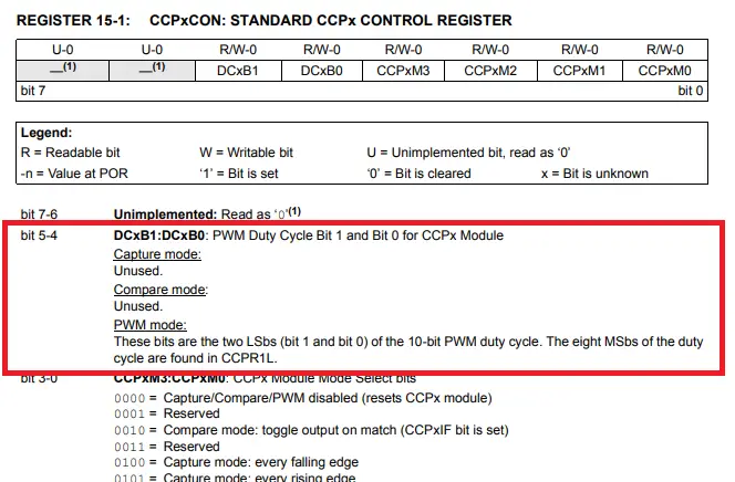
Step 04: The PWM duty cycle is specified by configuring CCPRxL register. The CCPR1 register is a 16 bit register which has 8 bit CCPR1L and 8 bit CCPR1H section. 8 bit CCPR1L is specified for taking value of duty cycle. But PIC18F4550 has 10 bit PWM module then what about rest of 2 bits? The last 2bit LSB is allocated in the bit number 5 and 4 in the CCPxCON register. Therefore, to write 10 bit PWM it will be CCPRxL:CCPxCON<5:4>. Check out page number 143 of the PIC18F4550 datasheet.
To calculate CCPRxL:CCPxCON<5:4> the formula is,

Let consider duty cycle = 40%. Then,

Now, generate a PWM signal whose frequency and duty cycle are 20 KHz and 40% respectively.
Step 05: Turn ON timer2 of PIC18F4550 by writing T2CONbits.TMR2ON=1. You can know more about it from the datasheet.
Now generate a PWM signal which duty cycle will be 40%,
#include <xc.h>
#define _XTAL_FREQ 20000000
void delay_ms(unsigned int);
void main()
{
    unsigned int duty_cycle;
    OSCCON=0x72;         /* set internal clock to 8MHz */
    TRISCbits.TRISC2=0;  /* Set CCP1 pin as output for PWM out */
    PR2=99;             /* load period value in PR2 register */
    CCPR1L=40;            /* load duty cycle */
    T2CON=0;             /* no pre-scalar,timer2 is off */
    CCP1CON=0x0C;        /* set PWM mode and no decimal value for PWM */
    TMR2=0;
    T2CONbits.TMR2ON=1;  /* Turn ON Timer2 */
    while(1)
    {
    }
}
For configuration bit settings of pic18f4550, please read our previous PIC microcontroller related tutorial.
The first few lines are written for configuring of PIC 18F4550 microcontroller. Select internal clock frequency 8 KHz with the help of OSCCON register. Set the C2 pin as PWM output by writing TRISCbits.TRISC2=0. The value of PR2 and CCPR1L are calculated above. Set the TIMER2 register by writing T2CONbits.TMR2ON=1. The PWM output is given below.
For troubleshooting, some extremely useful test equipment
[wptb id=890]
Controlling a LED brightness using PWM signal: The project
Controlling a LED brightness using PWM signal is very popular. In our second project we will make a PWM signal that’s duty cycle will vary 0 to 100% and LED brightness will vary according to duty cycle. Let’s try,
Circuit Diagram
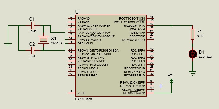
Full Code for MPLAB X IDE
#include <xc.h>
#define _XTAL_FREQ 20000000

inr duty_cycle;
void delay_ms(unsigned int);
void main()
{
    unsigned int duty_cycle;
    OSCCON=0x72;         /* set internal clock to 8MHz */
    TRISCbits.TRISC2=0;  /* Set CCP1 pin as output for PWM out */
    PR2=99;             /* load period value in PR2 register */
    CCPR1L=1;            /* load duty cycle */
    T2CON=0;             /* no pre-scalar,timer2 is off */
    CCP1CON=0x0C;        /* set PWM mode and no decimal value for PWM */
    TMR2=0;
    T2CONbits.TMR2ON=1;  /* Turn ON Timer2 */
    while(1)
    {
       for(duty_cycle=1;duty_cycle<99;duty_cycle++)
        {
            CCPR1L = duty_cycle;   //load duty cycle
            delay_ms(20);
        }
        delay_ms(500);

        for(duty_cycle=99;duty_cycle>1;duty_cycle--)
        {
            CCPR1L = duty_cycle;   //load duty cycle
            delay_ms(20);
        }
        delay_ms(500);
    }
}

void delay_ms(unsigned int val)
{
     unsigned int i,j;
        for(i=0;i<=val;i++)
            for(j=0;j<165;j++);      /*This count Provide delay of 1 ms for 8MHz Frequency */
 }
In while loop we vary our duty cycle 0 to 100%. After reaching duty cycle at 100% the percentage of duty cycle is decreased 100 to 1% and this time brightness of light is minimum. At 100% duty cycle the brightness is maximum. Check out the video that clear the concept.
So, We can control brightness of a light using PWM signal.