
In this tutorial, We will explain how to code a password based door lock system using PIC18F4550 microcontroller. We will also draw a circuit diagram for this project so that anyone can build this on his own.
Our other PIC Microcontroller related tutorials are:
- How to interface PIC Microcontroller with I2C sensors
- Everything about PIC Microcontroller Timer with example code
- How to generate PWM signal using PIC Microcontroller
Why do we need a Door Lock system?
Nobody doesn’t want that an unwanted person enters into their personal room because its increased the risk of losing their products. So modern hotels are secured their room with the password for protecting money and passport of the visitors. Therefore, we need to make a system that prevents of entering unauthorized person into a hotel room.
PIC18F4550 microcontroller Features & Specifications
- It is 8-bit microcontroller
- Total 40 pins
- 10-bit ADC
- 4 timers
- The frequency of an external oscillator is up to 48 MHZ
- The frequency of the internal oscillator is 32 kHz to 8 MHz (calibrated)
- It has 24 programmable I/O pins
- It has 2 analog comparators
- It has 2 PWM channels
Equipment required
- PIC 18F4550 microcontroller.
- 16×2 LCD display
- 3×4 keypad
- Buzzer
- 2N2222 NPN transistor
- 1 Resistor (1K)
- Wire
- Power Supply (5V)
For troubleshooting, some extremely useful test equipment
[wptb id=890]
Affiliate Disclosure: When you click on links to make a purchase, this can result in this website earning a commission. Affiliate programs and affiliations include, but are not limited to Amazon.com
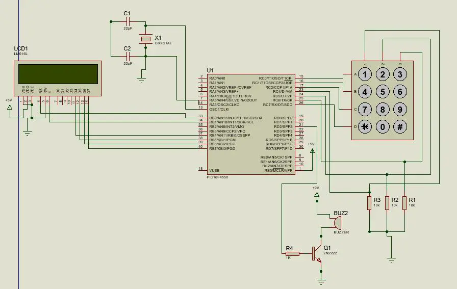
Circuit diagram
Code Explanation
The first few lines are configuring the microcontroller also define the Oscillator frequency that is 20KHz. we write some header file that helps us to run our code properly. Define PROT B for display and PORT C for keypad. We run our display 4 bits mode therefore, D4, D5, D6, D7 are connected with pin B4, B5, B6, and B7 of microcontroller. For buzzer define pin D2. Define some parameter for codding.
#define RS LATBbits.LATB0
#define EN LATBbits.LATB1
#define D4 LATBbits.LATB4
#define D5 LATBbits.LATB5
#define D6 LATBbits.LATB6
#define D7 LATBbits.LATB7
#define row1port LATCbits.LATC0
#define row2port LATCbits.LATC1
#define row3port LATCbits.LATC2
#define row4port LATCbits.LATC7
#define col1port PORTCbits.RC4
#define col2port PORTCbits.RC5
#define col3port PORTCbits.RC6
#define BUZZER LATDbits.LATD2
Now for keypad we write some function. We take 4×3 keypad and the characters of the keypad is written in the keyPadMatrix[] function. To initialize the keypad we take a function kbd_init().
char const keyPadMatrix[]=
{
'1','2','3',
'4','5','6',
'7','8','9',
'*','0','#',
0xFF
};
void kbd_init(){
TRISC = 0xF0;
PORTC = 0x00;
LATC = 0x00;
}
The purpose of this function is take first 4 bits of port C as input(LSB) and last 4 bits as output(MSB) and the hexa value is F0.
In kbd_getc() function we take input from user. To do this we make rows of the keypad as output and make column as input. The kbd_getc() scan all the four rows and if find any high pulse(1) from the column then it takes that character from the keyPadMatrix[] function. The scan time for each row is 1ms that why we take __delay_ms(1).
int kbd_getc(){
char key = 0, row;
for(row=0b00000001; row<0b00010000; row<<=1){
{
row1port = (row & 0x0001)>>0;
row2port = (row & 0x0002)>>1;
row3port = (row & 0x0004)>>2;
row4port = (row & 0x0008)>>3;
__delay_ms(1);
}
if(col1port)break; key++;
if(col2port)break; key++;
if(col3port)break; key++;

}
row1port = 0;
row2port = 0;
row3port = 0;
row4port = 0;
if(key!=old_key){
old_key=key;
return keyPadMatrix[key];
}
else{
return keyPadMatrix[0x0c];
}
}
To ON the LCD we need to send data to the LCD. We use 4 bit mode so we send 4 data to 4 pin of LCD. These data is sent by Lcd_SetBit(char data_bit) function. Comparing with some integer the data will be sent.
void Lcd_SetBit(char data_bit){ //Based on the Hex value Set the Bits of the Data Lines

    if(data_bit& 8)

        D1 = 1;

    else

        D1 = 0;

    if(data_bit& 4)

        D2 = 1;

    else

        D2 = 0;

    if(data_bit& 2)

        D3 = 1;

    else

        D3 = 0;

    if(data_bit& 1)

        D4 = 1;

    else

        D4 = 0;

}
To clear LCD screen we use Lcd_Clear() function. To set curser the Lcd_Set_Cursor(char a, char b) function is used. This function maintain the position of LCD print i.e. first and second row.
void Lcd_Set_Cursor(char a, char b){
    char temp,z,y;
    if(a== 1)
    {
      temp = 0x80 + b - 1; //80H is used to move the curser
        z = temp>>4; //Lower 8-bits
        y = temp & 0x0F; //Upper 8-bits
        Lcd_Cmd(z); //Set Row
        Lcd_Cmd(y); //Set Column
    }
    else if(a== 2){
        temp = 0xC0 + b - 1;
        z = temp>>4; //Lower 8-bits
        y = temp & 0x0F; //Upper 8-bits
        Lcd_Cmd(z); //Set Row
        Lcd_Cmd(y); //Set Column

    }
}
To start LCD the Lcd_Start() is used. And print into the LCD the Lcd_Print_Char(char data) is used. We need to write some information into this function.
void Lcd_Print_Char(char data){  //Send 8-bits through 4-bit mode
   char Lower_Nibble,Upper_Nibble;
   Lower_Nibble = data&0x0F;
   Upper_Nibble = data&0xF0;
   RS = 1;             // => RS = 1
   Lcd_SetBit(Upper_Nibble>>4);             //Send upper half by shifting by 4
   EN = 1;
  // for(int i=1130483; i<=0; i--)  NOP();
   EN = 0;
   Lcd_SetBit(Lower_Nibble); //Send Lower half
   EN = 1;
   //for(int i=1130483; i<=0; i--)  NOP();
   EN = 0;
}
In the main function print “Enter Password:” in the first line of LCD with the cursor position Lcd_Set_Cursor(2,1). Take 4 digits password with the help of keypad from the user.
if(keypress!=0xFF){
            keyboard =  keypress;
            inputPass[i] = keyboard;
            Lcd_Print_Char(inputPass[i]);
            //__delay_ms(300);
            i++;
            j++;
        }
After taking password we compare input password and preset password by the strcmp() function. If the password match the pre set password then the door is unlocked.
if(!strcmp(inputPass, pass)){
    Lcd_Clear();
    Lcd_Set_Cursor(1,1);
    Lcd_Print_String("Correct Password");
    Lcd_Set_Cursor(2,1);
    Lcd_Print_String("Door Unlocked");
    delay(2500000);
    //rotation_180();
    //__delay_ms(3000);
    }
If password is incorrect three times then the buzzer will glow.
else{
      Lcd_Clear();
    Lcd_Set_Cursor(1,1);
    Lcd_Print_String("Wrong Password");
    Lcd_Set_Cursor(2,1);
    Lcd_Print_String("Try Again...");
    error_count++;
    if(error_count == 3){
       BUZZER = 1;
        //__delay_ms(3000);
       delay(2500000);
        BUZZER = 0;
        error_count = 0;
    }
Full Code
// Configuration Bit Settings for pic18f4550
#include <xc.h>
#define _XTAL_FREQ 20000000 //20 Mhz

// CONFIG1L
#pragma config PLLDIV = 1       // PLL Prescaler Selection bits (No prescale (4 MHz oscillator input drives PLL directly))
#pragma config CPUDIV = OSC1_PLL2// System Clock Postscaler Selection bits ([Primary Oscillator Src: /1][96 MHz PLL Src: /2])
#pragma config USBDIV = 1       // USB Clock Selection bit (used in Full-Speed USB mode only; UCFG:FSEN = 1) (USB clock source comes directly from the primary oscillator block with no postscale)

// CONFIG1H
#pragma config FOSC = HS        // Oscillator Selection bits (HS oscillator)
#pragma config FCMEN = OFF      // Fail-Safe Clock Monitor Enable bit (Fail-Safe Clock Monitor disabled)
#pragma config IESO = OFF       // Internal/External Oscillator Switchover bit (Oscillator Switchover mode disabled)

// CONFIG2L
#pragma config PWRT = ON        // Power-up Timer Enable bit (PWRT enabled)
#pragma config BOR = ON         // Brown-out Reset Enable bits (Brown-out Reset enabled in hardware only (SBOREN is disabled))
#pragma config BORV = 3         // Brown-out Reset Voltage bits (Minimum setting 2.05V)
#pragma config VREGEN = OFF     // USB Voltage Regulator Enable bit (USB voltage regulator disabled)

// CONFIG2H
#pragma config WDT = OFF        // Watchdog Timer Enable bit (WDT disabled (control is placed on the SWDTEN bit))
#pragma config WDTPS = 32768    // Watchdog Timer Postscale Select bits (1:32768)

// CONFIG3H
#pragma config CCP2MX = OFF     // CCP2 MUX bit (CCP2 input/output is multiplexed with RB3)
#pragma config PBADEN = OFF     // PORTB A/D Enable bit (PORTB<4:0> pins are configured as digital I/O on Reset)
#pragma config LPT1OSC = OFF    // Low-Power Timer 1 Oscillator Enable bit (Timer1 configured for higher power operation)
#pragma config MCLRE = OFF      // MCLR Pin Enable bit (RE3 input pin enabled; MCLR pin disabled)

// CONFIG4L
#pragma config STVREN = OFF     // Stack Full/Underflow Reset Enable bit (Stack full/underflow will not cause Reset)
#pragma config LVP = OFF        // Single-Supply ICSP Enable bit (Single-Supply ICSP disabled)
#pragma config ICPRT = OFF      // Dedicated In-Circuit Debug/Programming Port (ICPORT) Enable bit (ICPORT disabled)
#pragma config XINST = OFF      // Extended Instruction Set Enable bit (Instruction set extension and Indexed Addressing mode disabled (Legacy mode))

// CONFIG5L
#pragma config CP0 = OFF        // Code Protection bit (Block 0 (000800-001FFFh) is not code-protected)
#pragma config CP1 = OFF        // Code Protection bit (Block 1 (002000-003FFFh) is not code-protected)
#pragma config CP2 = OFF        // Code Protection bit (Block 2 (004000-005FFFh) is not code-protected)
#pragma config CP3 = OFF        // Code Protection bit (Block 3 (006000-007FFFh) is not code-protected)

// CONFIG5H
#pragma config CPB = OFF        // Boot Block Code Protection bit (Boot block (000000-0007FFh) is not code-protected)
#pragma config CPD = OFF        // Data EEPROM Code Protection bit (Data EEPROM is not code-protected)

// CONFIG6L
#pragma config WRT0 = OFF       // Write Protection bit (Block 0 (000800-001FFFh) is not write-protected)
#pragma config WRT1 = OFF       // Write Protection bit (Block 1 (002000-003FFFh) is not write-protected)
#pragma config WRT2 = OFF       // Write Protection bit (Block 2 (004000-005FFFh) is not write-protected)
#pragma config WRT3 = OFF       // Write Protection bit (Block 3 (006000-007FFFh) is not write-protected)

// CONFIG6H
#pragma config WRTC = OFF       // Configuration Register Write Protection bit (Configuration registers (300000-3000FFh) are not write-protected)
#pragma config WRTB = OFF       // Boot Block Write Protection bit (Boot block (000000-0007FFh) is not write-protected)
#pragma config WRTD = OFF       // Data EEPROM Write Protection bit (Data EEPROM is not write-protected)

// CONFIG7L
#pragma config EBTR0 = OFF      // Table Read Protection bit (Block 0 (000800-001FFFh) is not protected from table reads executed in other blocks)
#pragma config EBTR1 = OFF      // Table Read Protection bit (Block 1 (002000-003FFFh) is not protected from table reads executed in other blocks)
#pragma config EBTR2 = OFF      // Table Read Protection bit (Block 2 (004000-005FFFh) is not protected from table reads executed in other blocks)
#pragma config EBTR3 = OFF      // Table Read Protection bit (Block 3 (006000-007FFFh) is not protected from table reads executed in other blocks)

// CONFIG7H
#pragma config EBTRB = OFF      // Boot Block Table Read Protection bit (Boot block (000000-0007FFh) is not protected from table reads executed in other blocks)

// #pragma config statements should precede project file includes.
// Use project enums instead of #define for ON and OFF.

#include <stdio.h>
#include <string.h>
#include <stdint.h>

#define RS LATBbits.LATB0
#define EN LATBbits.LATB1
#define D4 LATBbits.LATB4
#define D5 LATBbits.LATB5
#define D6 LATBbits.LATB6
#define D7 LATBbits.LATB7
#define row1port LATCbits.LATC0
#define row2port LATCbits.LATC1
#define row3port LATCbits.LATC2
#define row4port LATCbits.LATC7
#define col1port PORTCbits.RC4
#define col2port PORTCbits.RC5
#define col3port PORTCbits.RC6

#define SERVO LATDbits.LATD0
#define BUZZER LATDbits.LATD2

#define lcd_delay 300

#define LCDMaxLines 2
#define LCDMaxChars 16
#define LineOne 0x80
#define LineTwo 0xc0

#define BlankSpace ' '

/*
 Other Specific definition
 */

char const keyPadMatrix[]=
{
'1','2','3',
'4','5','6',
'7','8','9',
'*','0','#',
0xFF

};

uint8_t status=0, error_count=0;
char key, old_key;
uint8_t flag, i, j;
char inputPass[10];
char pass[] = "1234";

void kbd_init(){
TRISC = 0xF0;
PORTC = 0x00;
LATC = 0x00;

}

int kbd_getc(){

char key = 0, row;
for(row=0b00000001; row<0b00010000; row<<=1){
{
row1port = (row & 0x0001)>>0;
row2port = (row & 0x0002)>>1;
row3port = (row & 0x0004)>>2;
row4port = (row & 0x0008)>>3;
__delay_ms(1);
}
if(col1port)break; key++;
if(col2port)break; key++;
if(col3port)break; key++;

}
row1port = 0;
row2port = 0;
row3port = 0;
row4port = 0;
if(key!=old_key){
old_key=key;
return keyPadMatrix[key];
}
else{
return keyPadMatrix[0x0c];
}

}

void Lcd_SetBit(char data_bit){ //Based on the Hex value Set the Bits of the Data Lines
    if(data_bit& 1)
       D4 = 1;
    else
       D4 = 0;
    if(data_bit& 2)
        D5 = 1;
    else
        D5 = 0;
    if(data_bit& 4)
        D6 = 1;
    else
        D6 = 0;
    if(data_bit& 8)
        D7 = 1;
    else
        D7 = 0;
}


void Lcd_Cmd(char a){
    RS = 0;
    Lcd_SetBit(a); //Incoming Hex value
    EN  = 1;
     __delay_ms(1);
        EN  = 0;
}


Lcd_Clear(){
    Lcd_Cmd(0); //Clear the LCD
    Lcd_Cmd(1); //Move the curser to first position

}

void Lcd_Set_Cursor(char a, char b){
    char temp,z,y;
    if(a== 1)
    {
      temp = 0x80 + b - 1; //80H is used to move the curser
        z = temp>>4; //Lower 8-bits
        y = temp & 0x0F; //Upper 8-bits
        Lcd_Cmd(z); //Set Row
        Lcd_Cmd(y); //Set Column
    }

    else if(a== 2){
        temp = 0xC0 + b - 1;
        z = temp>>4; //Lower 8-bits
        y = temp & 0x0F; //Upper 8-bits
        Lcd_Cmd(z); //Set Row
        Lcd_Cmd(y); //Set Column
    }

}


void Lcd_Start() {
  Lcd_SetBit(0x00);
  for(int i=1065244; i<=0; i--)  NOP();
  Lcd_Cmd(0x03);
    __delay_ms(1);
  Lcd_Cmd(0x03);
    __delay_ms(2);
  Lcd_Cmd(0x03);
  Lcd_Cmd(0x02); //02H is used for Return home -> Clears the RAM and initializes the LCD
  Lcd_Cmd(0x02); //02H is used for Return home -> Clears the RAM and initializes the LCD
  Lcd_Cmd(0x08); //Select Row 1
  Lcd_Cmd(0x00); //Clear Row 1 Display
  Lcd_Cmd(0x0C); //Select Row 2
  Lcd_Cmd(0x00); //Clear Row 2 Display
  Lcd_Cmd(0x06);
}


void Lcd_Print_Char(char data){  //Send 8-bits through 4-bit mode
   char Lower_Nibble,Upper_Nibble;
   Lower_Nibble = data&0x0F;
   Upper_Nibble = data&0xF0;
   RS = 1;             // => RS = 1
   Lcd_SetBit(Upper_Nibble>>4);             //Send upper half by shifting by 4
   EN = 1;
  // for(int i=1130483; i<=0; i--)  NOP();
   EN = 0;
   Lcd_SetBit(Lower_Nibble); //Send Lower half
   EN = 1;
   //for(int i=1130483; i<=0; i--)  NOP();
   EN = 0;
}

void Lcd_Print_String(char *a) {
    int i;
    for(i=0;a[i]!='\0';i++)
    Lcd_Print_Char(a[i]);  //Split the string using pointers and call the Char function

}

void rotation_0(){
    unsigned int i;
    for(i=0; i<50; i++){
        SERVO = 1;
        __delay_us(800);
        SERVO = 0;
        __delay_us(19200);
    }
}

void rotation_180(){
    unsigned int i;
    for(i=0; i<50; i++){
        SERVO = 1;
        __delay_us(2200);
        SERVO = 0;
        __delay_us(17800);
    }
}

void main(void){
    TRISB = 0x00;
    TRISDbits.TRISD0 = 0;
    TRISDbits.TRISD2 = 0;
    kbd_init();
    Lcd_Start(); // This will initialise the lcd
    char keypress, keyboard = '0';
    i=0, j=1, flag=0;
    BUZZER = 0;
    while(1){
        rotation_0();
        Lcd_Clear();
        Lcd_Set_Cursor(1,1);
        Lcd_Print_String("Enter Password: ");
        Lcd_Set_Cursor(2,1);
      while(flag == 0){
          if(j>4){
          flag = 1;
          break;
          }
        keypress = kbd_getc();
        if(keypress!=0xFF){
            keyboard =  keypress;
            inputPass[i] = keyboard;
            Lcd_Print_Char(inputPass[i]);
            //__delay_ms(300);
            i++;
            j++;
        }
      }


 if(flag == 1){
  if(!strcmp(inputPass, pass)){
    Lcd_Clear();
    Lcd_Set_Cursor(1,1);
    Lcd_Print_String("Correct Password");
    Lcd_Set_Cursor(2,1);
    Lcd_Print_String("Door Unlocked");
    rotation_180();
    __delay_ms(3000);
    } else{
      Lcd_Clear();
    Lcd_Set_Cursor(1,1);
    Lcd_Print_String("Wrong Password");
    Lcd_Set_Cursor(2,1);
    Lcd_Print_String("Try Again...");
    error_count++;
    if(error_count == 3){
        BUZZER = 1;
        __delay_ms(3000);
        BUZZER = 0;
        error_count = 0;
    }
    __delay_ms(3000);
    }
    //Lcd_Clear();
    i = 0;
    j=1;
    //inputPass[0] = '\0';
    memset(inputPass,0,strlen(inputPass));
    flag = 0;
  }
  }
    }