
This tutorial will discuss how to interface a 4×4 matrix keypad with the STM32F103C8T6 Blue Pill Development Board using STM32CubeIDE and HAL libraries.
Structure & Working Mechanism of a 4*4 Keypad:
A 4×4 keypad is a matrix-style input device with 16 keys arranged in a 4-row by 4-column grid. It is commonly used for user input in embedded systems, such as calculators, password-protected locks, and other electronic interfaces.
Physical Layout
Each key acts as a switch at the intersection of a specific row and column. The keypad has a total of eight pins – four for rows and four for columns – allowing efficient scanning using a microcontroller. When a key is pressed, it connects a specific row to a column, creating a unique electrical connection that can be detected through software.
Electrical Wiring
- The 4 rows and 4 columns are connected using 8 GPIO pins of a microcontroller. Rows need to configure as Output and Columns as Input with Pull-up Resistors.
- Internally, each key acts as a switch between a row and a column.
Working Mechanism
- The microcontroller activates one row at a time and checks which column detects a key press.
- This process is called row-column scanning.
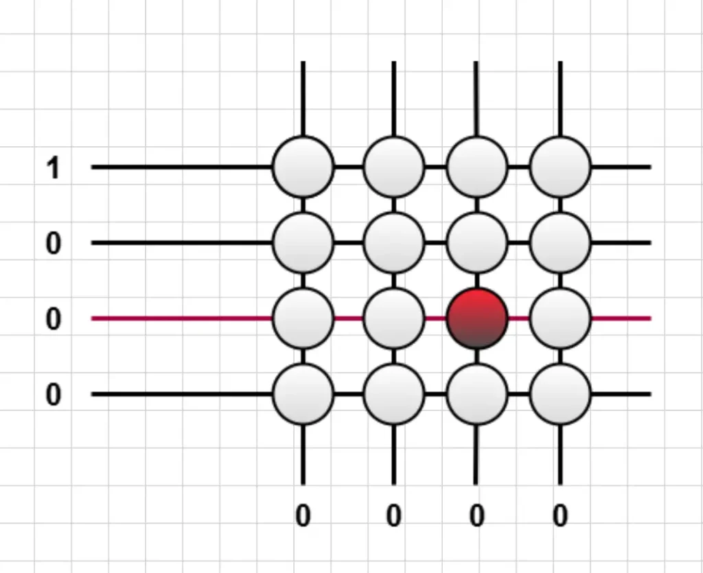
Figure: Row scanning started
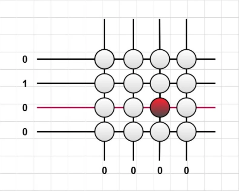
Figure: Row scanning in process
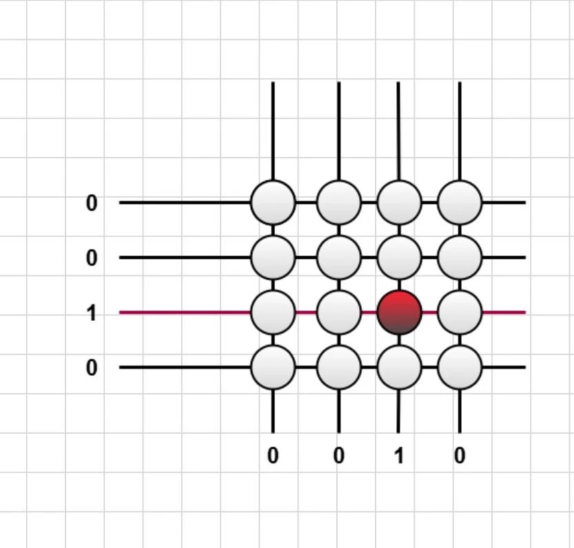
Figure: row and column are both high meaning the row and the column of the pressed button is determined
- The microcontroller activates one row at a time by setting it to LOW (0V) and keeps the others HIGH (5V or 3.3V).
- It then checks which column pin is pulled LOW, indicating a button press.
- If a key is pressed, it connects the active row to the corresponding column, and the microcontroller detects the press.
- The process is repeated for all rows to determine the exact key.
Applications of a 4×4 Keypad
- Password-protected systems (door locks, safes)
- ATMs and security panels
- Home automation controls
- Vending machines and ticketing systems
- Industrial control interfaces
Components List
| Component Name | Quantity | Purchase Link |
|---|---|---|
| STM32 Blue Pill | 1 | Amazon | AliExpress |
| 4×4 matrix keypad | 1 | Amazon | AliExpress |
| ST-LINK V2 | 1 | Amazon | AliExpress |
| Jumper Wires set | 1 | Amazon | AliExpress |
| Breadboard | 1 | Amazon | AliExpress |
Affiliate Disclosure: When you click on links to make a purchase, this can result in this website earning a commission. Affiliate programs and affiliations include, but are not limited to Amazon.com
Circuit Diagram
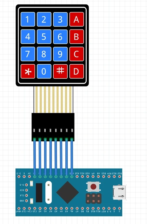
Connect the 8 pins of the 4*4 matrix keypad from A15 to B9 pins of the ST32F103C8 blue pill board.
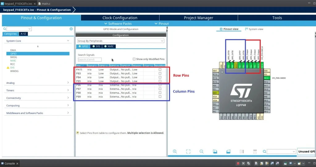
STM32CubeIDE Configuration
We configured Pin PB3, PB4, PB5, PA15 as Output for rows and Pin PB6, PB7, PB8, PB9 as External Interrupt for columns.
Check this below tutorial to know more about STM32 GPIO interrupt and how to configure a GPIO pins as External Interrupt: STM32 External Interrupt tutorial with HAL Example Code
To create a project in Stm32CubeIDE, please visit our previous tutorial. The link is given below:
Full Code
/* USER CODE END Header */
/* Includes ------------------------------------------------------------------*/
#include "main.h"

/* Private includes ----------------------------------------------------------*/
/* USER CODE BEGIN Includes */

/* USER CODE END Includes */

/* Private typedef -----------------------------------------------------------*/
/* USER CODE BEGIN PTD */

/* USER CODE END PTD */

/* Private define ------------------------------------------------------------*/
/* USER CODE BEGIN PD */

/* USER CODE END PD */

/* Private macro -------------------------------------------------------------*/
/* USER CODE BEGIN PM */

/* USER CODE END PM */

/* Private variables ---------------------------------------------------------*/

/* USER CODE BEGIN PV */
  GPIO_InitTypeDef GPIO_InitStructPrivate = {0};
  uint32_t previousMillis = 0;
  uint32_t currentMillis = 0;
  uint8_t keyPressed = 0;

/* USER CODE END PV */

/* Private function prototypes -----------------------------------------------*/
void SystemClock_Config(void);
static void MX_GPIO_Init(void);
/* USER CODE BEGIN PFP */

/* USER CODE END PFP */

/* Private user code ---------------------------------------------------------*/
/* USER CODE BEGIN 0 */
void HAL_GPIO_EXTI_Callback(uint16_t GPIO_Pin)
{
  currentMillis = HAL_GetTick();
  if (currentMillis - previousMillis > 10) {
    /*Configure GPIO pins : PB6 PB7 PB8 PB9 to GPIO_INPUT*/
    GPIO_InitStructPrivate.Pin = GPIO_PIN_6|GPIO_PIN_7|GPIO_PIN_8|GPIO_PIN_9;
    GPIO_InitStructPrivate.Mode = GPIO_MODE_INPUT;
    GPIO_InitStructPrivate.Pull = GPIO_NOPULL;
    GPIO_InitStructPrivate.Speed = GPIO_SPEED_FREQ_LOW;
    HAL_GPIO_Init(GPIOB, &GPIO_InitStructPrivate);

    HAL_GPIO_WritePin(GPIOA, GPIO_PIN_15, 1);
    HAL_GPIO_WritePin(GPIOB, GPIO_PIN_3, 0);
    HAL_GPIO_WritePin(GPIOB, GPIO_PIN_4, 0);
    HAL_GPIO_WritePin(GPIOB, GPIO_PIN_5, 0);
    if(GPIO_Pin == GPIO_PIN_6 && HAL_GPIO_ReadPin(GPIOB, GPIO_PIN_6))
    {
      keyPressed = 68; //ASCII value of D 68
    }
    else if(GPIO_Pin == GPIO_PIN_7 && HAL_GPIO_ReadPin(GPIOB, GPIO_PIN_7))
    {
      keyPressed = 35; //ASCII value of C 67
    }
    else if(GPIO_Pin == GPIO_PIN_8 && HAL_GPIO_ReadPin(GPIOB, GPIO_PIN_8))
    {
      keyPressed = 48; //ASCII value of B 66
    }
    else if(GPIO_Pin == GPIO_PIN_9 && HAL_GPIO_ReadPin(GPIOB, GPIO_PIN_9))
    {
      keyPressed = 42; //ASCII value of A 65
    }

    HAL_GPIO_WritePin(GPIOA, GPIO_PIN_15, 0);
    HAL_GPIO_WritePin(GPIOB, GPIO_PIN_3, 1);
    HAL_GPIO_WritePin(GPIOB, GPIO_PIN_4, 0);
    HAL_GPIO_WritePin(GPIOB, GPIO_PIN_5, 0);
    if(GPIO_Pin == GPIO_PIN_6 && HAL_GPIO_ReadPin(GPIOB, GPIO_PIN_6))
    {
      keyPressed = 67; //ASCII value of # 35
    }
    else if(GPIO_Pin == GPIO_PIN_7 && HAL_GPIO_ReadPin(GPIOB, GPIO_PIN_7))
    {
      keyPressed = 57; //ASCII value of 9 57
    }
    else if(GPIO_Pin == GPIO_PIN_8 && HAL_GPIO_ReadPin(GPIOB, GPIO_PIN_8))
    {
      keyPressed = 56; //ASCII value of 6 54
    }
    else if(GPIO_Pin == GPIO_PIN_9 && HAL_GPIO_ReadPin(GPIOB, GPIO_PIN_9))
    {
      keyPressed = 55; //ASCII value of 3 51
    }

    HAL_GPIO_WritePin(GPIOA, GPIO_PIN_15, 0);
    HAL_GPIO_WritePin(GPIOB, GPIO_PIN_3, 0);
    HAL_GPIO_WritePin(GPIOB, GPIO_PIN_4, 1);
    HAL_GPIO_WritePin(GPIOB, GPIO_PIN_5, 0);
    if(GPIO_Pin == GPIO_PIN_6 && HAL_GPIO_ReadPin(GPIOB, GPIO_PIN_6))
    {
      keyPressed = 66; //ASCII value of 0 48
    }
    else if(GPIO_Pin == GPIO_PIN_7 && HAL_GPIO_ReadPin(GPIOB, GPIO_PIN_7))
    {
      keyPressed = 54; //ASCII value of 8 56
    }
    else if(GPIO_Pin == GPIO_PIN_8 && HAL_GPIO_ReadPin(GPIOB, GPIO_PIN_8))
    {
      keyPressed = 53; //ASCII value of 5 53
    }
    else if(GPIO_Pin == GPIO_PIN_9 && HAL_GPIO_ReadPin(GPIOB, GPIO_PIN_9))
    {
      keyPressed = 52; //ASCII value of 2 50
    }

    HAL_GPIO_WritePin(GPIOA, GPIO_PIN_15, 0);
    HAL_GPIO_WritePin(GPIOB, GPIO_PIN_3, 0);
    HAL_GPIO_WritePin(GPIOB, GPIO_PIN_4, 0);
    HAL_GPIO_WritePin(GPIOB, GPIO_PIN_5, 1);
    if(GPIO_Pin == GPIO_PIN_6 && HAL_GPIO_ReadPin(GPIOB, GPIO_PIN_6))
    {
      keyPressed = 65; //ASCII value of * 42
    }
    else if(GPIO_Pin == GPIO_PIN_7 && HAL_GPIO_ReadPin(GPIOB, GPIO_PIN_7))
    {
      keyPressed = 51; //ASCII value of 7 55
    }
    else if(GPIO_Pin == GPIO_PIN_8 && HAL_GPIO_ReadPin(GPIOB, GPIO_PIN_8))
    {
      keyPressed = 50; //ASCII value of 4 52
    }
    else if(GPIO_Pin == GPIO_PIN_9 && HAL_GPIO_ReadPin(GPIOB, GPIO_PIN_9))
    {
      keyPressed = 49; //ASCII value of 1 49
    }

    HAL_GPIO_WritePin(GPIOA, GPIO_PIN_15, 1);
    HAL_GPIO_WritePin(GPIOB, GPIO_PIN_3, 1);
    HAL_GPIO_WritePin(GPIOB, GPIO_PIN_4, 1);
    HAL_GPIO_WritePin(GPIOB, GPIO_PIN_5, 1);
    /*Configure GPIO pins : PB6 PB7 PB8 PB9 back to EXTI*/
    GPIO_InitStructPrivate.Mode = GPIO_MODE_IT_RISING;
    GPIO_InitStructPrivate.Pull = GPIO_PULLDOWN;
    HAL_GPIO_Init(GPIOB, &GPIO_InitStructPrivate);
    previousMillis = currentMillis;
  }
}
/* USER CODE END 0 */

/**
  * @brief  The application entry point.
  * @retval int
  */
int main(void)
{

  /* USER CODE BEGIN 1 */

  /* USER CODE END 1 */

  /* MCU Configuration--------------------------------------------------------*/

  /* Reset of all peripherals, Initializes the Flash interface and the Systick. */
  HAL_Init();

  /* USER CODE BEGIN Init */

  /* USER CODE END Init */

  /* Configure the system clock */
  SystemClock_Config();

  /* USER CODE BEGIN SysInit */

  /* USER CODE END SysInit */

  /* Initialize all configured peripherals */
  MX_GPIO_Init();
  /* USER CODE BEGIN 2 */
   HAL_GPIO_WritePin(GPIOA, GPIO_PIN_15, 1);
      HAL_GPIO_WritePin(GPIOB, GPIO_PIN_3, 1);
      HAL_GPIO_WritePin(GPIOB, GPIO_PIN_4, 1);
      HAL_GPIO_WritePin(GPIOB, GPIO_PIN_5, 1);

  /* USER CODE END 2 */

  /* Infinite loop */
  /* USER CODE BEGIN WHILE */
  while (1)
  {
    /* USER CODE END WHILE */

    /* USER CODE BEGIN 3 */
  }
  /* USER CODE END 3 */
}
Please Note: Certain portions of the code, specifically those automatically generated by STM32CubeIDE, have been omitted.
Code Explanation
Global Variables
GPIO_InitTypeDef GPIO_InitStructPrivate = {0};
uint32_t previousMillis = 0;
uint32_t currentMillis = 0;
uint8_t keyPressed = 0;
- GPIO_InitStructPrivate: Used for configuring GPIO pins dynamically.
- previousMillis, currentMillis: Used for debouncing.
- keyPressed: Stores the ASCII value of the detected key.
Interrupt Service Routine: HAL_GPIO_EXTI_Callback()
void HAL_GPIO_EXTI_Callback(uint16_t GPIO_Pin)
{
  currentMillis = HAL_GetTick();
  if (currentMillis - previousMillis > 10) // Debouncing check
  {
    /* Configure rows as inputs */
    GPIO_InitStructPrivate.Pin = GPIO_PIN_6|GPIO_PIN_7|GPIO_PIN_8|GPIO_PIN_9;
    GPIO_InitStructPrivate.Mode = GPIO_MODE_INPUT;
    HAL_GPIO_Init(GPIOB, &GPIO_InitStructPrivate);

    /* Scan columns one by one */
    HAL_GPIO_WritePin(GPIOA, GPIO_PIN_15, 1);
    HAL_GPIO_WritePin(GPIOB, GPIO_PIN_3, 0);
    HAL_GPIO_WritePin(GPIOB, GPIO_PIN_4, 0);
    HAL_GPIO_WritePin(GPIOB, GPIO_PIN_5, 0);

    if(GPIO_Pin == GPIO_PIN_6 && HAL_GPIO_ReadPin(GPIOB, GPIO_PIN_6))
      keyPressed = 68; // ASCII of 'D'
    else if(GPIO_Pin == GPIO_PIN_7 && HAL_GPIO_ReadPin(GPIOB, GPIO_PIN_7))
      keyPressed = 35; // ASCII of '#'
    else if(GPIO_Pin == GPIO_PIN_8 && HAL_GPIO_ReadPin(GPIOB, GPIO_PIN_8))
      keyPressed = 48; // ASCII of '0'
    else if(GPIO_Pin == GPIO_PIN_9 && HAL_GPIO_ReadPin(GPIOB, GPIO_PIN_9))
      keyPressed = 42; // ASCII of '*'

    /* Repeat for other columns */
    HAL_GPIO_WritePin(GPIOA, GPIO_PIN_15, 0);
    HAL_GPIO_WritePin(GPIOB, GPIO_PIN_3, 1);
    if(GPIO_Pin == GPIO_PIN_6 && HAL_GPIO_ReadPin(GPIOB, GPIO_PIN_6))
      keyPressed = 67; // ASCII of 'C'
    else if(GPIO_Pin == GPIO_PIN_7 && HAL_GPIO_ReadPin(GPIOB, GPIO_PIN_7))
      keyPressed = 57; // ASCII of '9'
    else if(GPIO_Pin == GPIO_PIN_8 && HAL_GPIO_ReadPin(GPIOB, GPIO_PIN_8))
      keyPressed = 56; // ASCII of '8'
    else if(GPIO_Pin == GPIO_PIN_9 && HAL_GPIO_ReadPin(GPIOB, GPIO_PIN_9))
      keyPressed = 55; // ASCII of '7'

    /* Continue scanning for remaining columns */
    HAL_GPIO_WritePin(GPIOB, GPIO_PIN_3, 0);
    HAL_GPIO_WritePin(GPIOB, GPIO_PIN_4, 1);
    if(GPIO_Pin == GPIO_PIN_6 && HAL_GPIO_ReadPin(GPIOB, GPIO_PIN_6))
      keyPressed = 66; // ASCII of 'B'
    else if(GPIO_Pin == GPIO_PIN_7 && HAL_GPIO_ReadPin(GPIOB, GPIO_PIN_7))
      keyPressed = 54; // ASCII of '6'
    else if(GPIO_Pin == GPIO_PIN_8 && HAL_GPIO_ReadPin(GPIOB, GPIO_PIN_8))
      keyPressed = 53; // ASCII of '5'
    else if(GPIO_Pin == GPIO_PIN_9 && HAL_GPIO_ReadPin(GPIOB, GPIO_PIN_9))
      keyPressed = 52; // ASCII of '4'

    HAL_GPIO_WritePin(GPIOB, GPIO_PIN_4, 0);
    HAL_GPIO_WritePin(GPIOB, GPIO_PIN_5, 1);
    if(GPIO_Pin == GPIO_PIN_6 && HAL_GPIO_ReadPin(GPIOB, GPIO_PIN_6))
      keyPressed = 65; // ASCII of 'A'
    else if(GPIO_Pin == GPIO_PIN_7 && HAL_GPIO_ReadPin(GPIOB, GPIO_PIN_7))
      keyPressed = 51; // ASCII of '3'
    else if(GPIO_Pin == GPIO_PIN_8 && HAL_GPIO_ReadPin(GPIOB, GPIO_PIN_8))
      keyPressed = 50; // ASCII of '2'
    else if(GPIO_Pin == GPIO_PIN_9 && HAL_GPIO_ReadPin(GPIOB, GPIO_PIN_9))
      keyPressed = 49; // ASCII of '1'

    /* Reset columns to HIGH */
    HAL_GPIO_WritePin(GPIOA, GPIO_PIN_15, 1);
    HAL_GPIO_WritePin(GPIOB, GPIO_PIN_3, 1);
    HAL_GPIO_WritePin(GPIOB, GPIO_PIN_4, 1);
    HAL_GPIO_WritePin(GPIOB, GPIO_PIN_5, 1);

    /* Set rows back to interrupt mode */
    GPIO_InitStructPrivate.Mode = GPIO_MODE_IT_RISING;
    HAL_GPIO_Init(GPIOB, &GPIO_InitStructPrivate);

    previousMillis = currentMillis;
  }
}
The function detects which key was pressed by toggling one column at a time and checking which row received a HIGH signal.
Result
The detected key’s ASCII value is stored in keyPressed.