In this tutorial, we will explain the basic principle of External Interrupt in a microcontroller-based system. To get you started, we will guide you on how to interface with External Interrupt in the STM32 Microcontroller by building an example project using the STM32 Nucleo Development Board and STM32CubeIDE. We will use the onboard USER BUTTON of the Nucleo Development Board for the project.
You may also like reading:
What is an Interrupt in a Microcontroller?
An interrupt is a mechanism that enables the microcontroller to pause its current execution and divert its attention to handle a specific event. These events, known as interrupt requests, can be triggered by various sources, such as external signals, timers, I2C, UART, or other peripheral devices.
When an interrupt occurs, the microcontroller stops its current task, saves its state, and jumps to a predefined section of code called the Interrupt Service Routine (ISR).
How Does Interrupt Service Routine (ISR) Work?
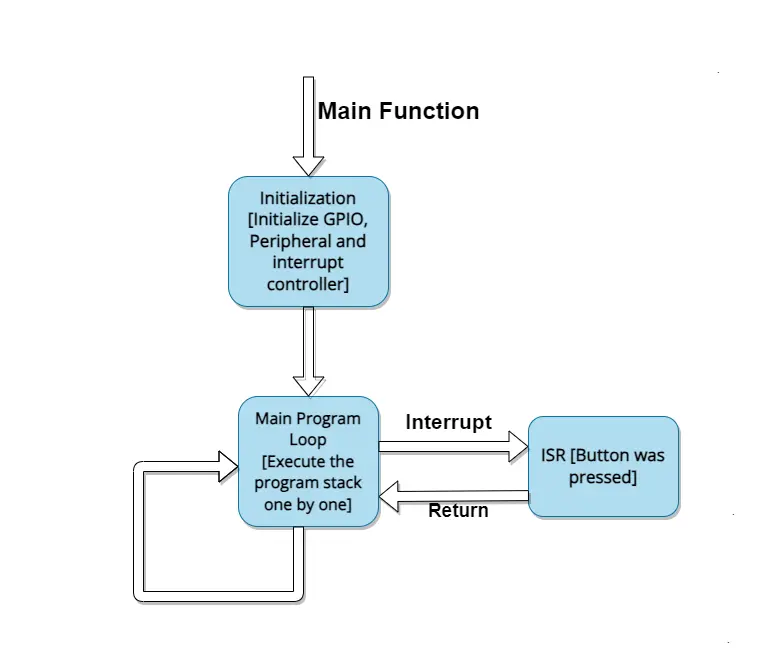
The Interrupt Service Routine (ISR) is a specialized function or set of functions that the microcontroller executes in response to a specific interrupt event. When an interrupt occurs, the microcontroller follows a series of steps to seamlessly transition from normal execution to the ISR:
- Interrupt Occurrence: An external event, such as a button press, a timer reaching a specific value, or a sensor signal change, triggers an interrupt request.
- Interrupt Signal: The microcontroller recognizes the interrupt request and interrupts its current execution.
- Context Saving: The processor saves the current context, including the program counter, register values, and flags, to the stack. This step ensures that the interrupted task can later resume without losing its state.
- Vector Table Lookup: The microcontroller uses a vector table to find the address of the corresponding ISR associated with the triggered interrupt. The vector table is a table of function pointers that directs the processor to the appropriate ISR.
- ISR Execution: The processor jumps to the address specified by the vector table, initiating the execution of the ISR. The ISR contains the code to handle the specific event that triggered the interrupt.
- Interrupt Handling: Within the ISR, the microcontroller performs the necessary operations to address the interrupt, such as reading sensor data, updating variables, or responding to external input.
- Context Restoration: After completing the ISR, the processor restores the saved context from the stack, allowing the interrupted task to continue from where it left off.
- Return from Interrupt: The processor executes a return from interrupt (RTI) instruction, which retrieves the program counter and other context information from the stack, allowing the microcontroller to resume its normal execution.
Understanding External Interrupts in STM32 Microcontroller
External interrupts on STM32 microcontrollers are external events, such as button presses, sensor outputs, timer interrupts, or other signals. These interrupts allow the microcontroller to interrupt its current execution and immediately handle the external event. You need to know some terms before handling STM32 external interrupt and they are:
- MCU Interrupt Design: The MCU is designed to efficiently manage and respond to various interrupt sources. The microcontroller has a set of interrupt lines, each associated with specific peripherals or events. External interrupts are typically associated with GPIO pins and can be configured to trigger interrupts on rising edges, falling edges, or both.
- NVIC (Nested Vector Interrupt Controller): The NVIC is a key component of the ARM Cortex-M architecture, which is the core architecture used in STM32 microcontrollers. It manages the interrupt priorities and controls the execution flow during interrupts. The NVIC allows for nested interrupts, meaning that a higher-priority interrupt can preempt a lower-priority interrupt, enabling efficient handling of multiple interrupt sources.
- Configuring External Interrupts: To use external interrupts on STM32 microcontrollers, you need to configure the associated GPIO pin as an input and set up the external interrupt parameters. This involves configuring the trigger edge [rising, falling, or both], enabling the interrupt request, and setting the interrupt priority.
STM32 External (GPIO) Interrupt Project
In this section of the tutorial, we will build a small project by using the STM32 External (GPIO) interrupt feature by interfacing a push button and an LED. We will toggle the STM32-nucleo onboard LED by using the user push button which is also on the development board. The push button will configure for the external GPIO interrupt.
Component List
| Component Name | Quantity | Links |
|---|---|---|
| STM32 Nucleo Dev. Board | 1 | Amazon.com |
Some extremely useful test equipment for troubleshooting electronic circuits
| Equipment Name | Links |
|---|---|
| Best Oscilloscope for Professionals | Amazon.com |
| Best Oscilloscope for Beginners and Students | Amazon.com |
| Best Budget Multimeter | Amazon.com |
| Adjustable Bench Power Supply | Amazon.com |
Affiliate Disclosure: When you click on links to make a purchase, this can result in this website earning a commission. Affiliate programs and affiliations include, but are not limited to Amazon.com
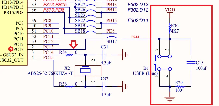
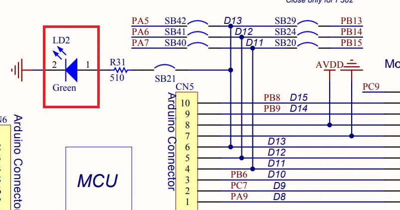
Circuit Diagram
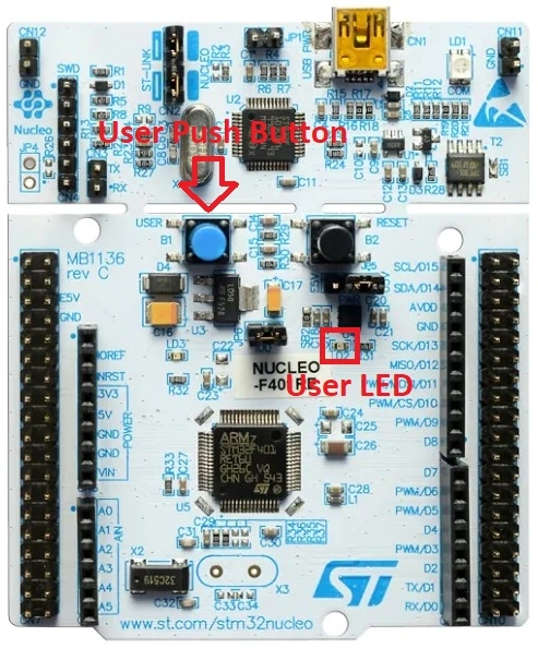
As we are using the STM32 nucleo-f446re development board, we will configure the onboard user button for external (GPIO) interrupt which is connected to PORT C Pin 13 (PC13).
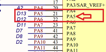
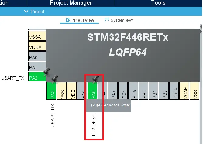
We will also configure the onboard USER LED as output which is connected to PORT A Pin 5 of the STM32 Nucleo development board. We will toggle the LED by using the onboard PUSH BUTTON which will configure in interrupt mode.
Preparing STM32CubeIDE for the project
For project creation in Stm32CubeIDE, please visit your previous tutorial. The link is given below:
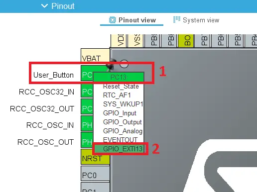
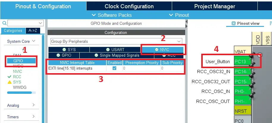
After creating the project in Stm32CubeIDE, go to the Device Configuration Tool of STM32CubeIDE and configure the pin PC13 [User_Button] as a GPIO interrupt.
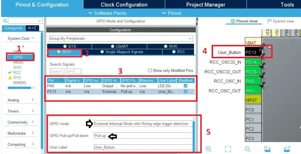
Then go to System Core > GPIO. Open the GPIO tab and active the following configuration:
- GPIO Mode
- GPIO Pull-up/Pull-down
We are using GPIO Mode as an External interrupt with Rising edge and Pull-up.
After completing the GPIO configuration click on the NVIC tab and enable the EXTI line [15:10] interrupt. EXTI is the External Interrupt/Event controller of the STM32 microcontroller. Please check your datasheet to learn about the NVIC and EXTI lines of your MCU.
Then configure the pin PA5 pin as GPIO output for the user led and generate the code for STM32CubeIDE.
Project Code and Description
In the main.c file of STM32CubeIDE, we handle the interrupt service routine by using the HAL_GPIO_EXTI_Callback function. Which is defined in Drivers>STM32F4xx_HAL_Driver>stm32f4xx_hal_gpio.c file as __weak attribute.
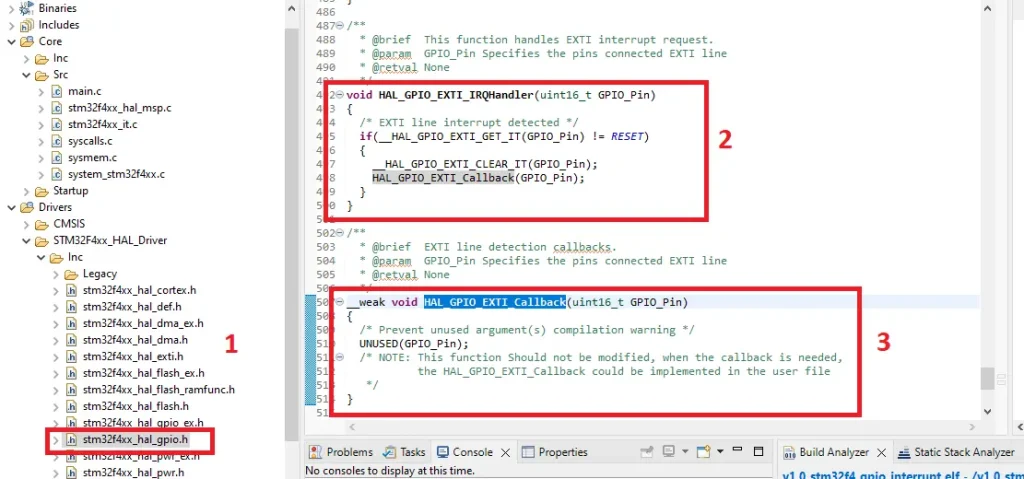
In the callback function, we just toggle the LED (ON-OFF) by using the USER PUSH BUTTON of the NUCLEO board.
void HAL_GPIO_EXTI_Callback(uint16_t GPIO_Pin)
{
  if(GPIO_Pin == GPIO_PIN_13){
	  HAL_GPIO_TogglePin(GPIOA, GPIO_PIN_5);
  }
}
Full Project Code
/* USER CODE END Header */
/* Includes */
#include "main.h"

/* Private variables */
 UART_HandleTypeDef huart2;

/* Private function prototypes */
void SystemClock_Config(void);
static void MX_GPIO_Init(void);
static void MX_USART2_UART_Init(void);

/**
  * @brief  The application entry point.
  * @retval int
  */
int main(void)
{
  /* MCU Configuration */

  /* Reset of all peripherals, Initializes the Flash interface and the Systick. */
  HAL_Init();

  /* Configure the system clock */
  SystemClock_Config();

  /* Initialize all configured peripherals */
  MX_GPIO_Init();
  MX_USART2_UART_Init();

  /* Infinite loop */
  /* USER CODE BEGIN WHILE */
  while (1)
  {
    /* USER CODE END WHILE */
  }
}

// EXTI line 13 detection callbacks function
// for PC13
void HAL_GPIO_EXTI_Callback(uint16_t GPIO_Pin)
{
  if(GPIO_Pin == GPIO_PIN_13){
	  HAL_GPIO_TogglePin(GPIOA, GPIO_PIN_5);
  }
}
Please Note: Certain portions of the code, specifically those automatically generated by STM32CubeIDE, have been omitted.
Output of the Code