
In this tutorial, we will explain the basic principle of SPI and how it works. We will also discuss SPI bus configuration and SPI modes. After that, we will talk about the hardware overview of SPI peripherals in the STM32 microcontroller. To get you started, we will configure the SPI peripherals of the Nucleo-f446re development board using STM32CubeIDE and discuss some of the important HAL API functions for interfacing with various SPI devices.
You may also like reading:
- STM32 External Interrupt with HAL Example Code
- STM32 Timer tutorial using interrupt
- STM32 UART / USART tutorial with HAL code example
- Stm32 I2C communication with HAL code example
SPI Basics
SPI stands for Serial Peripheral Interface. It is a synchronous serial communication protocol commonly used to transfer data between a master device and one or more peripheral (Slave) devices. SPI is widely used in embedded systems, such as microcontrollers and other digital devices, for communication between integrated circuits like Micro SD cards, Display,s or EEPROM Chip.
SPI Wiring
SPI lines have different names and they vary from manufacturer to manufacturer. Typically, SPI uses four signal lines:
- CLK/SCK/SCLK (Serial Clock): The clock signal generated by the master to synchronize data transfer.
- SDI(Serial Data In)/MISO (Master In, Slave Out): The line through which the slave sends data to the master.
- SDO(Serial Data Out)/MOSI (Master Out, Slave In): The line through which the master sends data to the slave.
- SS(Slave Select)/CS (Chip Select): The line used by the master to select a specific slave for communication.
How SPI Data Communication Works
In this section, we will discuss how data communication takes place between master and slave. When you explore the SPI peripheral of your microcontroller, you always see the shift registers. SPI communication is based on Shift Registers.
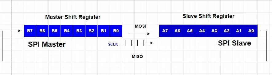
SPI is a very simple technique of data exchange. From the above diagram, Let’s assume we have two shift registers. One is a master and another is a slave. Master and Slave both shift registers have 8 bits. MOSI of master connected to MOSI of slave and MISO of master connected to MISO of slave. A clock is also required to push the data.
We will send the data from the master shift register to the slave shift register. After one clock cycle, the B0 bit from the master shift register moves to the A7 bit of the slave shift register in the MOSI line. So, data is shifted one bit and the A0 bit of slave takes place to MSB position (B7) of the master shift register. In this sequence, after 8 clock cycles, all the 8-bit of the master shift register successfully transfer to the slave shift register.
SPI Bus Configuration: Full Duplex, Half Duplex, and Simplex
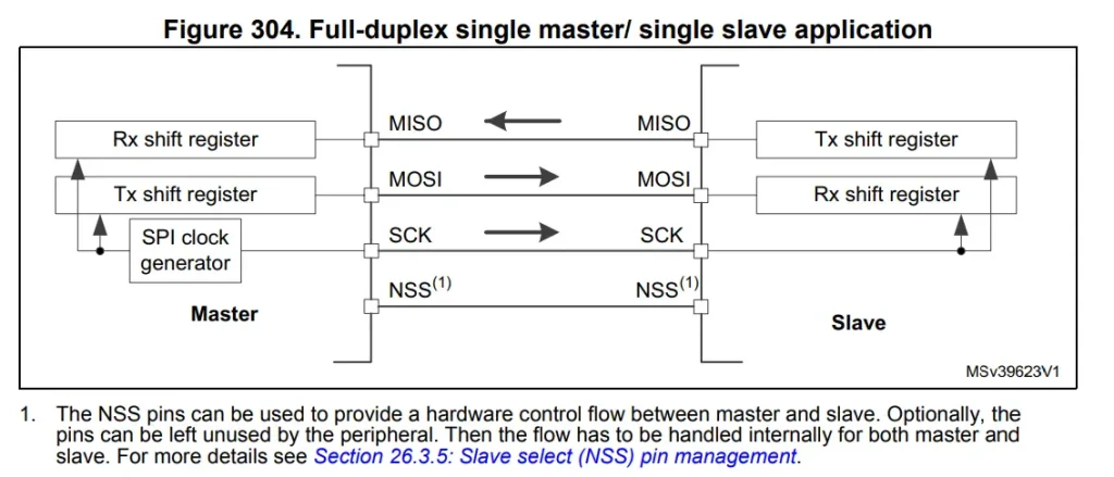
Full Duplex: In full-duplex SPI communication, data can be sent and received simultaneously. The master sends data on the MOSI line while simultaneously receiving data on the MISO line. This bidirectional communication is a key feature of SPI. By default, SPI is configured as Full Duplex communication.
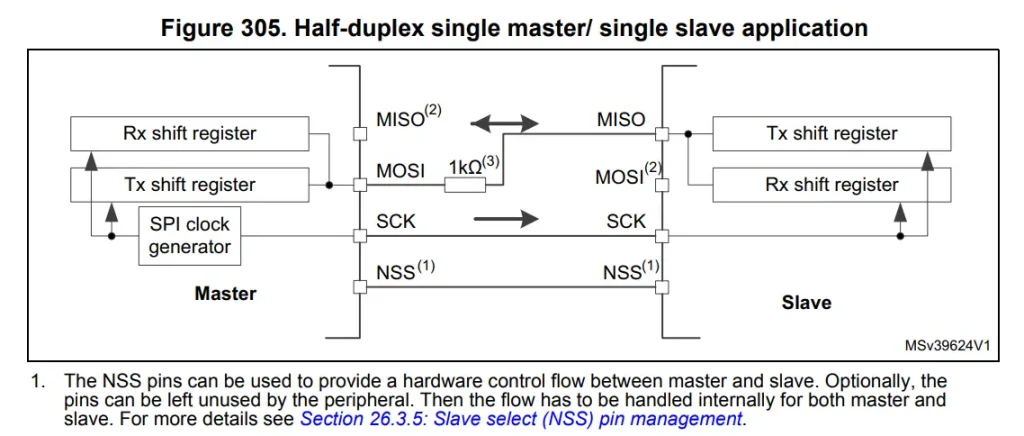
Half Duplex: Half-duplex SPI allows communication in both directions, but not at the same time. The master and slave devices take turns sending and receiving data. This can be useful in scenarios where full-duplex communication is not necessary. It also saves one GPIO pin of the MCU.
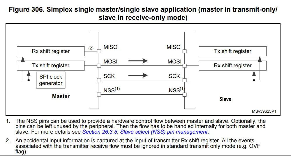
Simplex: Simplex SPI communication is unidirectional, meaning data is transmitted in only one direction. While this is less common in typical SPI setups, it can be useful in specific applications where one-way communication is sufficient like display interfacing.
SPI Modes (CPOL and CPHA)
During SPI Communication, receive and transmit operations are performed simultaneously. The communication format depends on the clock phase, clock polarity, and data frame format. To be able to communicate together, the master and slave devices must follow the same communication format.
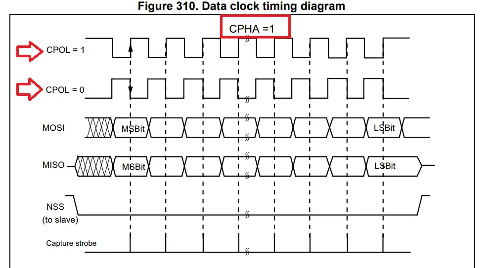
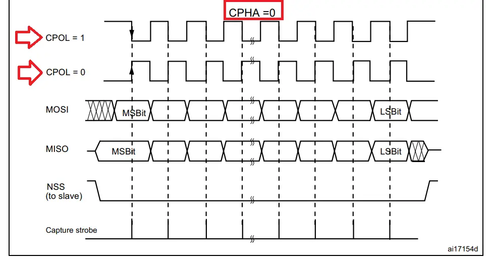
The two key parameters that define the communication characteristics of SPI are CPOL (Clock Polarity) and CPHA (Clock Phase). These parameters determine the idle state of the clock signal (CPOL) and the timing relationship between data and clock signals (CPHA).
CPOL, or Clock Polarity, dictates the level of the clock signal when it is in its idle state. In SPI, the clock can be either active-high (CPOL=0) or active-low (CPOL=1) during idle periods. The choice of CPOL is essential to ensure proper synchronization between the master and the peripheral slave devices.
On the other hand, CPHA, or Clock Phase, defines the edge of the clock signal on which data is sampled or latched. It can be either on the first (CPHA=0) or second (CPHA=1) edge of the clock cycle.
4 different SPI modes
| Mode | CPOL (Clock Polarity) | CPHA (Clock Phase) |
|---|---|---|
| 0 | 0 | 0 |
| 1 | 0 | 1 |
| 2 | 1 | 0 |
| 3 | 1 | 1 |
Slave select (CS/NSS) pin management
- Software CS management: In software management, we want to manage the slave using the software which means we don’t want any physical Slave Select pin, and instead we can use any GPIO pin from the microcontroller as the Slave Select pin.
- Hardware CS management: For hardware slave select management we have to use the actual slave select fixed pin to control the slave device. The NSS/CS signal is driven low as soon as the SPI is enabled in master mode and the pin is low until the SPI is disabled.
STM32 SPI Hardware Overview
The STM32 SPI hardware typically includes multiple SPI peripherals, each with its own set of registers and features. Users can configure key parameters such as the baud rate, data frame format, and master or slave mode through the control registers.
The STM32 SPI module supports a variety of data frame formats, including 8 or 16 bits, with options for MSB (Most Significant Bit) or LSB (Least Significant Bit) first.
Additionally, the STM32 SPI hardware provides flexibility in clock polarity (CPOL) and clock phase (CPHA) settings, enabling users to adapt the communication protocol to the requirements of connected peripherals.
DMA (Direct Memory Access) support further enhances efficiency by allowing data transfers to occur without CPU intervention. The STM32 SPI module also offers hardware-based NSS (Slave Select) management and supports both master and slave configurations, making it well-suited for a broad range of applications.
Please check your STM32 microcontroller datasheet to know more about its feathers.
STM32 SPI Functional Block Diagram
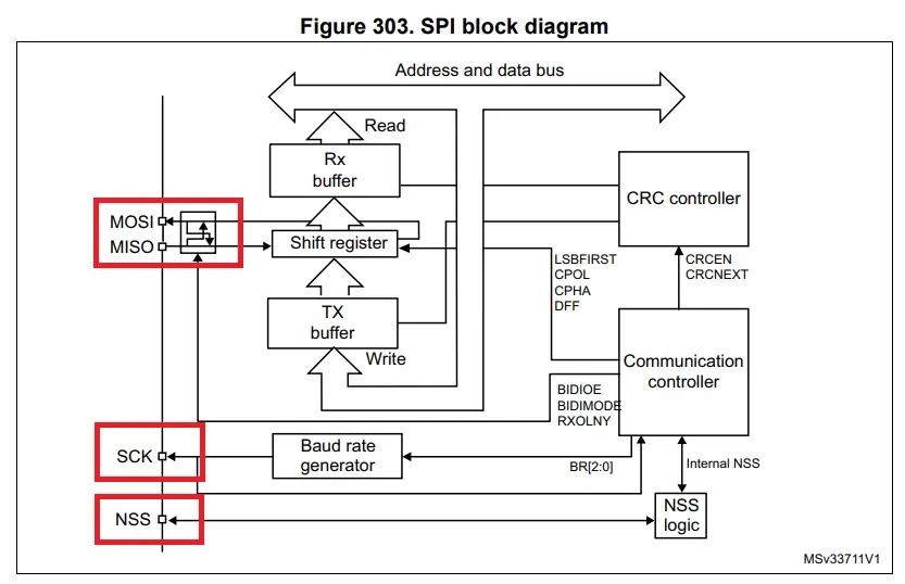
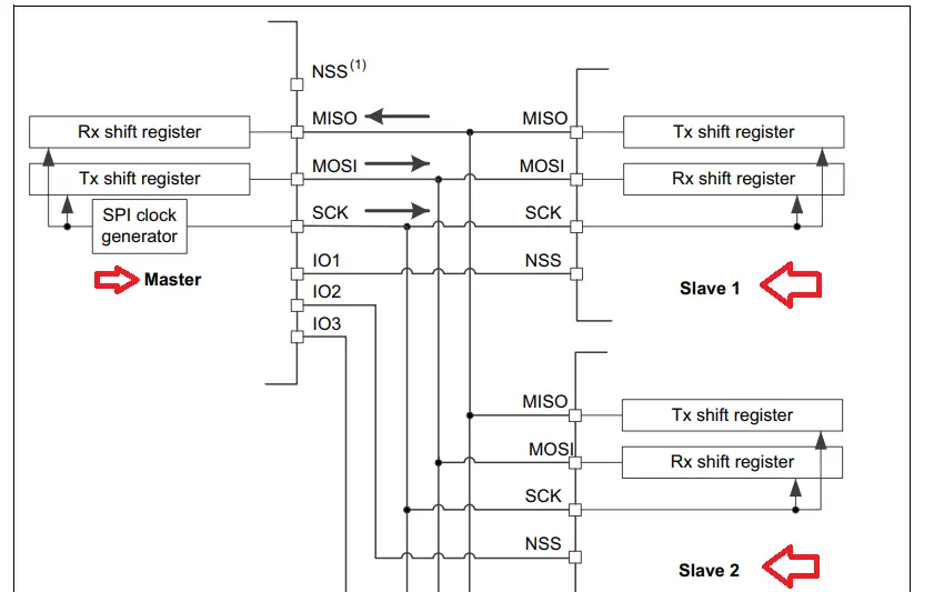
The SPI bus allows communication between one master device and one or more slave devices. The bus consists of at least two wires – one for the clock signal and the other for synchronous data transfer. Other signals can be added depending on the data exchange between SPI nodes and their slave-select signal management.
Setting up the Development Environment Using STM32CubeIDE
In this section, we will configure the SPI peripheral of the STM32F448RE microcontroller using STM32CubeIDE for demonstration purposes. So that you can configure the peripheral on your own for your MCU. All the processes are almost the same but you need to check your datasheet first for the SPI peripheral overview before configuring.
Required development board for this tutorial: Nucleo-f446re
Affiliate Disclosure: When you click on the above link to make a purchase, this can result in this website earning a commission from Amazon.
For project creation in Stm32CubeIDE, please visit your previous tutorial. The link is given below:
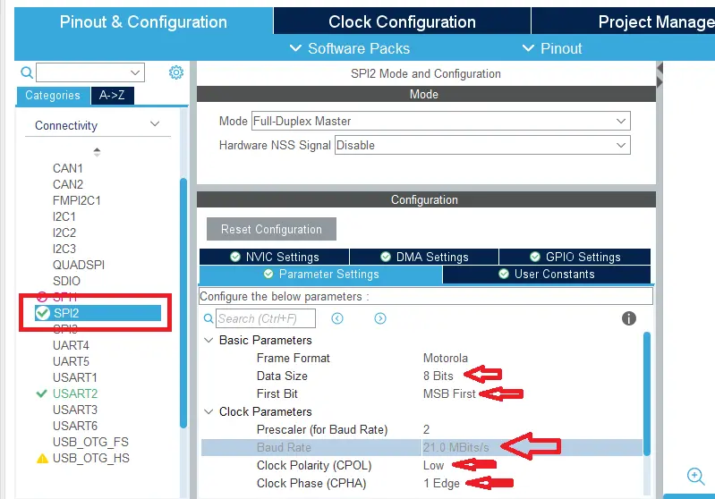
Step 01: Go to the Connectivity Section, select SPI2, and set Mode to Full-Duplex Master. Change the Data Size to 8- bits and change the Prescaler to 32 (we want the Baud Rate to be around 1.3 Mbits/s). Change NSSP Mode (slave-select pulse mode) to Disabled.
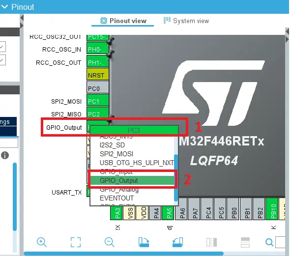
Step 02: After that set the pin PC3 on our Nucleo Board as GPIO output mode to select the chip select (CS) line manually.
STM32 SPI HAL Functions APIs
SPI Blocking Mode Function APIs
Data Transmit function from master to slave:
HAL_SPI_Transmit(SPI_HandleTypeDef *hspi, uint8_t *pData, uint16_t Size, uint32_t Timeout);
Parameters description:
- hspi: pointer to a SPI_HandleTypeDef structure that contains the configuration information for SPI module.
- pData: pointer to data buffer.
- Size: amount of data to be sent
- Timeout: Timeout duration
- return: HAL status
Data Reception function from slave to master:
HAL_SPI_Receive(SPI_HandleTypeDef *hspi, uint8_t *pData, uint16_t Size, uint32_t Timeout);
Parameters description:
- hspi: pointer to a SPI_HandleTypeDef structure that contains the configuration information for SPI module.
- pData: pointer to data buffer
- Size: amount of data to be received
- Timeout: Timeout duration
- return: HAL status
Data Transmit and Receive at the same function:
HAL_SPI_TransmitReceive(SPI_HandleTypeDef *hspi, uint8_t *pTxData, uint8_t *pRxData, uint16_t Size, uint32_t Timeout);
Parameters description:
- hspi: pointer to a SPI_HandleTypeDef structure that contains the configuration information for SPI module.
- pTxData: pointer to transmission data buffer.
- pRxData: pointer to reception data buffer.
- Size: amount of data to be sent and received.
- Timeout: Timeout duration.
- Return: HAL status
SPI Interrupt Mode Function APIs
Data Transmit function from master to slave (Interrupt Mode):
HAL_SPI_Transmit_IT(SPI_HandleTypeDef *hspi, uint8_t *pData, uint16_t Size);
Callback function after successfully transmitting data:
void HAL_SPI_TxCpltCallback(SPI_HandleTypeDef * hspi)
{
    // Data Transmission Done. Do Something
}
Data Reception function from slave to master (Interrupt Mode):
HAL_SPI_Receive_IT(SPI_HandleTypeDef *hspi, uint8_t *pData, uint16_t Size);
Callback function after successfully receiving data:
void HAL_SPI_RxCpltCallback(SPI_HandleTypeDef * hspi)
{
    // Data Reception Done. Do Something.
}
Data Transmit and Receive at the same function (Interrupt Mode):
HAL_SPI_TransmitReceive_IT(SPI_HandleTypeDef *hspi, uint8_t *pTxData, uint8_t *pRxData, uint16_t Size);
Callback function after successfully sending-receiving data:
void HAL_SPI_TxRxCpltCallback(SPI_HandleTypeDef * hspi)
{
    // Data sending-receiving. Do Something
}
SPI DMA Mode Function APIs
Data Transmit function from master to slave (DMA Mode):
HAL_SPI_Transmit_DMA(SPI_HandleTypeDef * hspi, uint8_t * pData, uint16_t Size);
Callback function after successfully transmitting data:
void HAL_SPI_TxCpltCallback(SPI_HandleTypeDef * hspi)
{
    // Data Transmission Done. Do Something
}
Data Reception function from slave to master (DMA Mode):
HAL_SPI_Receive_DMA(SPI_HandleTypeDef *hspi, uint8_t *pData, uint16_t Size);
Callback function after successfully receiving data:
void HAL_SPI_RxCpltCallback(SPI_HandleTypeDef * hspi)
{
    // Data Reception Done. Do Something
}
Data Transmit and Receive at the same function (DMA Mode):
HAL_SPI_TransmitReceive_DMA(SPI_HandleTypeDef *hspi, uint8_t *pTxData, uint8_t *pRxData, uint16_t Size);
Callback function after successfully sending-receiving data:
void HAL_SPI_TxRxCpltCallback(SPI_HandleTypeDef * hspi)
{
    // Data sending-receiving. Do Something
}