
In this tutorial, we will cover the STM32 USART peripheral. We will also cover how to handle UART protocol in STM32 and create an example project in interrupt mode using the STM32 NUCLEO-F446RE development board that will transmit and receive data between stm32 and the host computer via USB port.
You may also like reading:
- STM32 UART/USART tutorial using DMA with HAL code example
- STM32 SPI Interfacing with HAL Example Code
Our other STM32 related tutorials are:
- STM32 ADC Interfacing with HAL code example
- STM32 ADC tutorial using DMA with HAL Code Example
- Getting Started with FreeRTOS in STM32
- STM32 Timer tutorial using interrupt
- How to create a project in stm32CubeMX for Keil uvision Ide
- How to create stm32 project in stm32cubeide with example code
Component List for the project
| Component Name | Quantity | Purchase Link |
|---|---|---|
| STM32 NUCLEO Development Board | 1 | Amazon |
| Breadboard | 1 | Amazon |
| Jumper wire pack | 1 | Amazon |
| USB Mini-B cable | 1 | Amazon |
For troubleshooting, some extremely useful test equipment
| Equipment Name | Purchase Link |
|---|---|
| Best Oscilloscope for Professionals | Amazon |
| Best Oscilloscope for Beginners | Amazon |
| Logic Analyzer | Amazon |
| Best Budget Multimeter | Amazon |
| Adjustable Bench Power Supply | Amazon |
Affiliate Disclosure: When you click on links to make a purchase, this can result in this website earning a commission. Affiliate programs and affiliations include, but are not limited to Amazon.com
STM32 USART Peripheral
USART means universal synchronous asynchronous receiver transmitter. It is just a hardware that enables the device to communicate using serial protocol. It also has an asynchronous mode called UART. STM32 microcontroller supports both protocols. In this tutorial, we use UART for communication.
Some of the main features of the STM32 USART peripheral are:
- Full duplex, asynchronous communications
- NRZ standard format (Mark/Space)
- Programmable data word length (8 or 9 bits)
- Configurable stop bits – support for 1 or 2 stop bits
- Transmitter clock output for synchronous transmission
- Single-wire half-duplex communication
To know more about the peripheral please check your selected stm32 microcontroller datasheet.
How to handle UART in STM32
Polling Mode
The first way is just to poll for the hardware resource until it’s ready to move on to the next step in the program instructions. However, it’s not an efficient way to handle UART and the CPU will end up wasting so much time in a busy or waiting state.
This will happen for both transmission and reception. You have to wait until the current bytes of data are transmitted so you can start the next transition and so on. You could use the STM32 UART interrupts mode for solving the issue.
Interrupts Mode
In that mode, you don’t have to wait to finish the data transmission. You have a signal when UART is done with the transmission or reception and ready for service. This saves a lot of time and CPU overload. Interrupts mode is always the best way to handle events like that.
In some Critical applications like medical devices or time-critical applications, we need everything to be as perfect and on time. The main problem with interrupts is that we can’t expect when data arrive or during which task. That can harmful for such kind of application. To overcome this kind of succession, we can use Interrupt with DMA.
DMA Mode
Direct memory access (DMA) is a method that allows an input or output (I/O) device to send or receive data directly to or from the main memory of the processor without the help of the CPU to speed up memory operations. To facilitate the data transfers, the I2C protocol features a DMA capability implementing a simple request/response protocol.
DMA requests are mainly generated by the Data Register of the processor. Register becoming empty in transmission and full in reception. Data transfer mainly happens between the peripheral to memory, so the CPU can perform the other tasks. This will end up saving a lot of time and is considered to be the most efficient way to handle this peripheral to memory data transfer and vice versa.
UART configuration in STM32CubeIDE
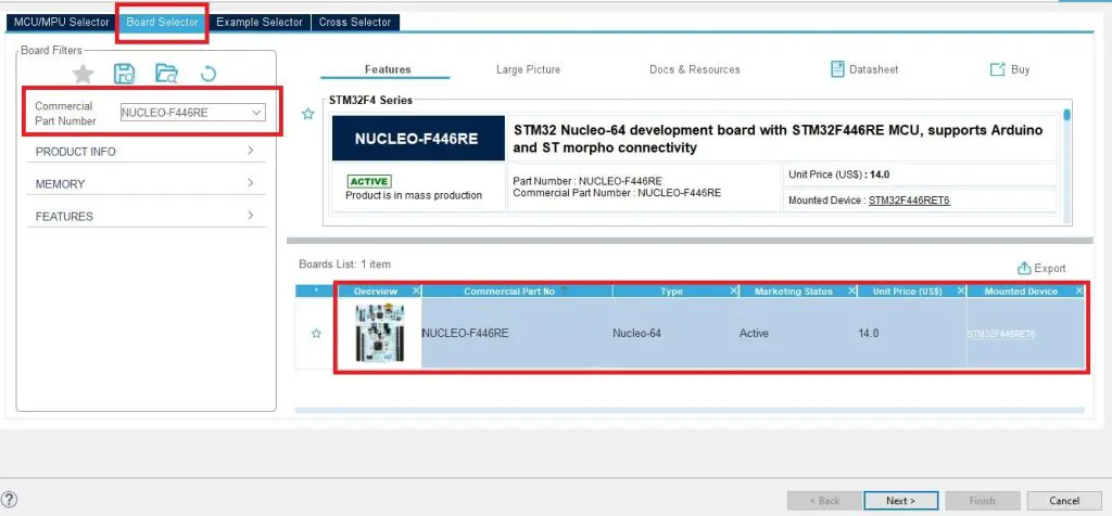
Open your stm32CubeIDE the go to File>New>Stm32 Project. Then open the Board Select tab and Enter your stm32 development board name. In this tutorial, we are using the NUCLEO-F446RE board. Then click Next.
After that add your Project Name on the next page and click Finish.
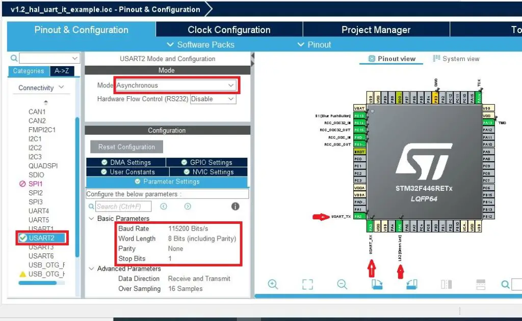
By default, STM32CubeIDE set up all the necessary files and peripherals under the HAL (Hardware Abstraction Layer) when you create the project. The NUCLEO-F446RE development board has a built-in ST-Link debugger and STM32CubeIDE configure PA2 and PA3 as UART Tx and Rx pin respectively.
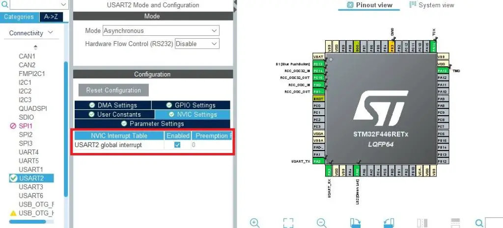
We also enable the global interrupt from the NVIC settings as we are going to use the interrupt mode for this example.
Code Explanation
As we mentioned earlier that we are going to use the interrupt mode in this example project. For that, we already configured the global interrupt from the configuration settings.
As we are using the windows operating system, we use Tera Term (terminal emulator application) to communicate between our microcontroller and PC. You can download Tera Term from this Link.
For transmitting data in interrupt mode, we use a HAL function called HAL_UART_Transmit_IT()
HAL_UART_Transmit_IT(UART_HandleTypeDef *huart, const uint8_t *pData, uint16_t Size)
For receiving data in interrupt mode, we use a HAL function called HAL_UART_Receive_IT()
HAL_UART_Receive_IT(UART_HandleTypeDef *huart, uint8_t *pData, uint16_t Size)
HAL transmit complete callback function
void HAL_UART_TxCpltCallback(UART_HandleTypeDef *huart){
     // write some code when transmission is complete
}
HAL reception complete callback function
void HAL_UART_RxCpltCallback(UART_HandleTypeDef *huart){
     // write some code when reception is complete
}
Here is the full code
main.c file
#include "main.h"
#include<string.h>

void SystemClock_Config(void);
static void MX_GPIO_Init(void);
static void MX_USART2_UART_Init(void);

UART_HandleTypeDef huart2; //UART_2 handle variable

char *user_data = "The application is running\r\n"; //demo data for transmission-

uint8_t data_buffer[100]; // data buffer
uint8_t recvd_data; // receive buffer
uint32_t count=0; // count how many bytes are received

int main(void)
{
  HAL_Init();
  SystemClock_Config();
  MX_GPIO_Init();
  MX_USART2_UART_Init();

  HAL_UART_Transmit_IT(&huart2,(uint8_t*)user_data,strlen(user_data)); //Transmit data in interrupt mode
  HAL_UART_Receive_IT(&huart2,&recvd_data,1); //receive data from data buffer interrupt mode
  while (1){
	  HAL_GPIO_TogglePin(GPIOA, LD2_Pin); //loggle the user led which is connected to GPIO PA5
	  HAL_Delay(500); //delay 500 milisecond
  }

}

//UART 2 transmission complete callback
void HAL_UART_TxCpltCallback(UART_HandleTypeDef *huart)
{
	memset(user_data, 0, strlen(user_data)); //empty the transmission data buffer
}

//UART 2 receive complete callback
void HAL_UART_RxCpltCallback(UART_HandleTypeDef *huart)
{

	 if(recvd_data == '\r') //when enter is pressed go to this condition
	 {
		 data_buffer[count++]='\r';
		 HAL_UART_Transmit(huart,data_buffer,count,HAL_MAX_DELAY); //transmit the full sentence again
		 memset(data_buffer, 0, count); // enpty the data buffer
	 }
	 else
	 {
		 data_buffer[count++] = recvd_data; // every time when interrput is happen, received 1 byte of data
	 }
	 HAL_UART_Receive_IT(&huart2,&recvd_data,1); //start next data receive interrupt


}

/**
  * @brief System Clock Configuration
  * @retval None
  */
void SystemClock_Config(void)
{
  RCC_OscInitTypeDef RCC_OscInitStruct = {0};
  RCC_ClkInitTypeDef RCC_ClkInitStruct = {0};

  /** Configure the main internal regulator output voltage
  */
  __HAL_RCC_PWR_CLK_ENABLE();
  __HAL_PWR_VOLTAGESCALING_CONFIG(PWR_REGULATOR_VOLTAGE_SCALE3);

  /** Initializes the RCC Oscillators according to the specified parameters
  * in the RCC_OscInitTypeDef structure.
  */
  RCC_OscInitStruct.OscillatorType = RCC_OSCILLATORTYPE_HSI;
  RCC_OscInitStruct.HSIState = RCC_HSI_ON;
  RCC_OscInitStruct.HSICalibrationValue = RCC_HSICALIBRATION_DEFAULT;
  RCC_OscInitStruct.PLL.PLLState = RCC_PLL_ON;
  RCC_OscInitStruct.PLL.PLLSource = RCC_PLLSOURCE_HSI;
  RCC_OscInitStruct.PLL.PLLM = 16;
  RCC_OscInitStruct.PLL.PLLN = 336;
  RCC_OscInitStruct.PLL.PLLP = RCC_PLLP_DIV4;
  RCC_OscInitStruct.PLL.PLLQ = 2;
  RCC_OscInitStruct.PLL.PLLR = 2;
  if (HAL_RCC_OscConfig(&RCC_OscInitStruct) != HAL_OK)
  {
    Error_Handler();
  }

  /** Initializes the CPU, AHB and APB buses clocks
  */
  RCC_ClkInitStruct.ClockType = RCC_CLOCKTYPE_HCLK|RCC_CLOCKTYPE_SYSCLK
                              |RCC_CLOCKTYPE_PCLK1|RCC_CLOCKTYPE_PCLK2;
  RCC_ClkInitStruct.SYSCLKSource = RCC_SYSCLKSOURCE_PLLCLK;
  RCC_ClkInitStruct.AHBCLKDivider = RCC_SYSCLK_DIV1;
  RCC_ClkInitStruct.APB1CLKDivider = RCC_HCLK_DIV2;
  RCC_ClkInitStruct.APB2CLKDivider = RCC_HCLK_DIV1;

  if (HAL_RCC_ClockConfig(&RCC_ClkInitStruct, FLASH_LATENCY_2) != HAL_OK)
  {
    Error_Handler();
  }
}

/**
  * @brief USART2 Initialization Function
  * @param None
  * @retval None
  */
static void MX_USART2_UART_Init(void)
{
  huart2.Instance = USART2;
  huart2.Init.BaudRate = 115200;
  huart2.Init.WordLength = UART_WORDLENGTH_8B;
  huart2.Init.StopBits = UART_STOPBITS_1;
  huart2.Init.Parity = UART_PARITY_NONE;
  huart2.Init.Mode = UART_MODE_TX_RX;
  huart2.Init.HwFlowCtl = UART_HWCONTROL_NONE;
  huart2.Init.OverSampling = UART_OVERSAMPLING_16;
  if (HAL_UART_Init(&huart2) != HAL_OK)
  {
    Error_Handler();
  }

}

/**
  * @brief GPIO Initialization Function
  * @param None
  * @retval None
  */
static void MX_GPIO_Init(void)
{
  GPIO_InitTypeDef GPIO_InitStruct = {0};

  /* GPIO Ports Clock Enable */
  __HAL_RCC_GPIOC_CLK_ENABLE();
  __HAL_RCC_GPIOH_CLK_ENABLE();
  __HAL_RCC_GPIOA_CLK_ENABLE();
  __HAL_RCC_GPIOB_CLK_ENABLE();

  /*Configure GPIO pin Output Level */
  HAL_GPIO_WritePin(LD2_GPIO_Port, LD2_Pin, GPIO_PIN_RESET);

  /*Configure GPIO pin : B1_Pin */
  GPIO_InitStruct.Pin = B1_Pin;
  GPIO_InitStruct.Mode = GPIO_MODE_IT_FALLING;
  GPIO_InitStruct.Pull = GPIO_NOPULL;
  HAL_GPIO_Init(B1_GPIO_Port, &GPIO_InitStruct);

  /*Configure GPIO pin : LD2_Pin */
  GPIO_InitStruct.Pin = LD2_Pin;
  GPIO_InitStruct.Mode = GPIO_MODE_OUTPUT_PP;
  GPIO_InitStruct.Pull = GPIO_NOPULL;
  GPIO_InitStruct.Speed = GPIO_SPEED_FREQ_LOW;
  HAL_GPIO_Init(LD2_GPIO_Port, &GPIO_InitStruct);

}

/**
  * @brief  This function is executed in case of error occurrence.
  * @retval None
  */
void Error_Handler(void)
{
  /* USER CODE BEGIN Error_Handler_Debug */
  /* User can add his own implementation to report the HAL error return state */
  __disable_irq();
  while (1)
  {
  }
  /* USER CODE END Error_Handler_Debug */
}

#ifdef  USE_FULL_ASSERT
/**
  * @brief  Reports the name of the source file and the source line number
  *         where the assert_param error has occurred.
  * @param  file: pointer to the source file name
  * @param  line: assert_param error line source number
  * @retval None
  */
void assert_failed(uint8_t *file, uint32_t line)
{
  /* USER CODE BEGIN 6 */
  /* User can add his own implementation to report the file name and line number,
     ex: printf("Wrong parameters value: file %s on line %d\r\n", file, line) */
  /* USER CODE END 6 */
}
#endif /* USE_FULL_ASSERT */