In this tutorial, we will explain the basic principles of Analog to Digital Converter (ADC) and Direct Memory Access (DMA) of the STM32 microcontroller. To get you started, we will show you how to interface multiple channels ADC using DMA in STM32 Nucleo development Board and STM32Cube IDE.
You may also like reading:
Our other STM32-related tutorials are:
- How to interface STM32 with RS485 (Modbus) sensors
- STM32 PWM Tutorial: HAL Example Code Included
- Interfacing STM32 with I2C LCD : HAL example code included
- How to create a project in stm32CubeMX for Keil uvision Ide
- How to create stm32 project in stm32cubeide with example code
- STM32 UART / USART tutorial with HAL code example
- Stm32 Bluetooth module HC-05 interfacing with HAL code example
STM32 ADC peripheral overview
The STM32 microcontrollers provide an Analog-to-Digital Converter (ADC) peripheral that allows you to convert analog signals into digital values. The ADC peripheral is a crucial feature for many embedded applications that involve reading analog sensors or acquiring analog signals for processing.
Here is an overview of the STM32 ADC peripheral:
Resolution
The ADC resolution determines the number of digital bits in the converted result. STM32 microcontrollers offer various ADC resolutions, such as 12-bit, 16-bit, or even higher. Like, STM32F446RE MCU supports 12-bit ADC.
Conversion Modes
The ADC can operate in different conversion modes:
- Single Conversion Mode: In this mode, a single conversion is triggered, and the ADC converts one analog input channel at a time.
- Continuous Conversion Mode: In continuous mode, the ADC continuously converts multiple channels without the need for retriggering.
- Scan Mode: The scan mode allows you to convert multiple channels sequentially with a single trigger.
Sampling Time
The sampling time refers to the duration during which the ADC samples the analog input voltage. It is essential to set an appropriate sampling time to allow the ADC to capture the analog signal accurately.
For example, if the ADC clock is 14 MHz and has a sampling time of 1.5 cycles then the ADC conversion time is 1us. Check your STM32 Microcontroller datasheet to read more about ADC Sampling and Covertion time.
Channels
The STM32 ADC peripheral supports multiple channels for converting multiple analog inputs. Each channel can be individually configured with specific settings such as sampling time, resolution, and input voltage range.
Conversion Trigger
The ADC conversion can be triggered in various ways:
- Software Trigger: Conversion is initiated by software control.
- External Trigger: An external event or signal triggers the conversion. This can be a timer, an external interrupt, or a specific signal level change.
Interrupts and DMA
The ADC peripheral can generate interrupts upon the completion of conversion or when specific conditions are met. Additionally, you can use DMA to transfer the converted data to memory without CPU intervention.
Analog Watchdog
The ADC peripheral often includes an analog watchdog feature. This allows you to set thresholds to monitor the converted values and trigger an interrupt or take other actions if the converted value falls outside the specified range.
Calibration
STM32 ADCs typically provide calibration mechanisms to improve accuracy. These calibration techniques compensate for factors like offset and gain errors.
It’s important to consult the specific microcontroller’s reference manual and datasheet for detailed information on the ADC peripheral’s capabilities, registers, and configuration options. The STM32Cube software development platform from STMicroelectronics also offers libraries, examples, and configuration tools to simplify the ADC peripheral’s usage.
DMA in STM32 Microcontroller
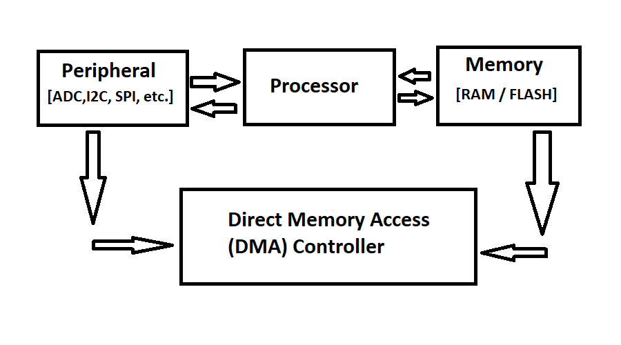
DMA stands for Direct Memory Access. DMA is a feature available in many microcontrollers, including those in the STM32 series, that allows for efficient data transfer between peripherals and memory without involving the CPU.
The DMA controller acts as an intermediary between the peripherals and the memory, enabling direct data transfers. Instead of the CPU being responsible for moving data between peripherals and memory, the DMA controller takes over this task, freeing up the CPU to perform other tasks.
The DMA controller operates independently and can transfer data in various modes, such as single, circular, or burst mode. It can transfer data to or from peripherals, memory, or even between different memory locations.
Using DMA can greatly enhance the performance of a microcontroller, especially in scenarios where frequent and high-speed data transfers are required, such as audio processing from ADC, data logging, or communication protocols like UART, SPI, or I2C.
STM32 Multiple Channels ADC interfacing using DMA: The Project
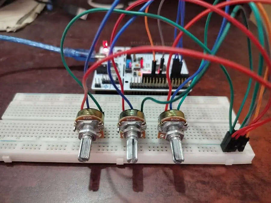
In this section of the tutorial, we will explore the STM32 ADC peripheral in DMA mode by interfacing with three potentiometers. We will connect the three potentiometers to three of the ADC channels (ADC 1) and collect the data from the three channels at the same time by using the DMA controller without interrupting the processor. We will show the value of the ADC Channels in a serial terminal software (like Tera Term) of the computer by using UART.
Component List
| Component Name | Quantity | Purchase Link |
|---|---|---|
| STM32 Nucleo Development Board | 1 | Amazon |
| 10K Potentiometer | 3 | Amazon |
| Breadboard | 1 | Amazon |
| Jumper Wire Pack | 1 | Amazon |
For troubleshooting, some extremely useful test equipment
| Equipment Name | Purchase Link |
|---|---|
| Best Oscilloscope for Professionals | Amazon |
| Best Oscilloscope for Beginners and Students | Amazon |
| Logic Analyzer | Amazon |
| Best Budget Multimeter | Amazon |
| Adjustable Bench Power Supply | Amazon |
Affiliate Disclosure: When you click on links to make a purchase, this can result in this website earning a commission. Affiliate programs and affiliations include, but are not limited to Amazon.com
Circuit Diagram
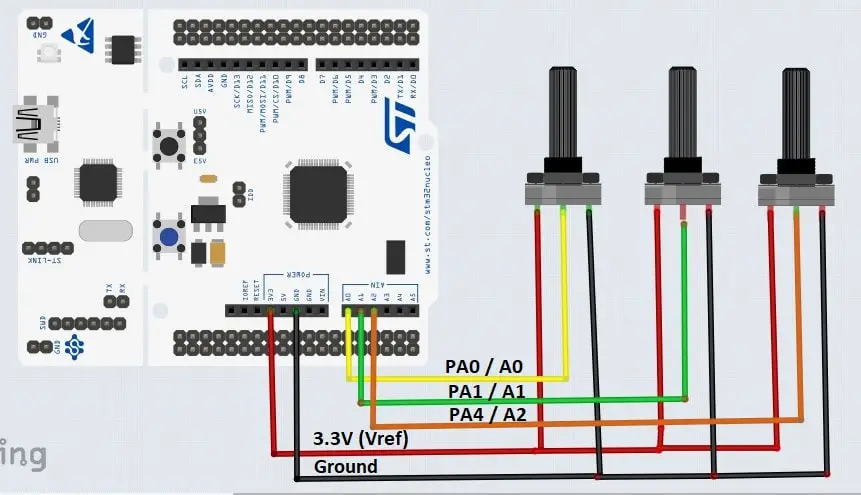
Pin connection
| STM32 NUCLEO-F446RE Pin | Potentiometer 1 | Potentiometer 2 | Potentiometer 3 |
|---|---|---|---|
| 3.3 Volt | Vcc | Vcc | Vcc |
| Ground | Ground | Ground | Ground |
| PA0 / A0 | Output Pin | ||
| PA1 / A1 | Output Pin | ||
| PA3 / A2 | Output Pin |
Preparing STM32Cube IDE for the project
For project creation in Stm32CubeIDE, please visit your previous tutorial. Link is given below:
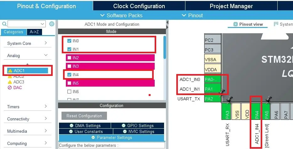
After creating the project in Stm32CubeIDE, Enable the ADC1 peripheral from the device configuration tools of Stm32CubeIDE. For, ADC1 we configure GPIO A pin 0 (PA0) as ADC Channel 1, GPIO A pin 1 (PA1) as ADC Channel 2, and GPIO A pin 4 (PA4) as ADC Channel 3 respectively.
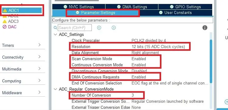
After enabling ADC channels, click on ADC1 Parameters Settings and configure the following parameters:
- Select the ADC Resulation as a 12-bits
- Enable Scan Conversion Mode
- Enable Continuous Conversion Mode
- Enable DMA Continous Request
- Select the Number of conversions. In our case, we enable 3 channels for conversion
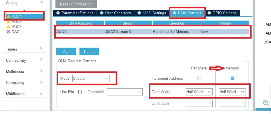
Next, click on DMA Settings and select DMA Request as ADC1. Go to DMA Request Settings and select the Circular Mode for continuous DMA Request. Also, the data direction should be marked as Peripheral to Memory.
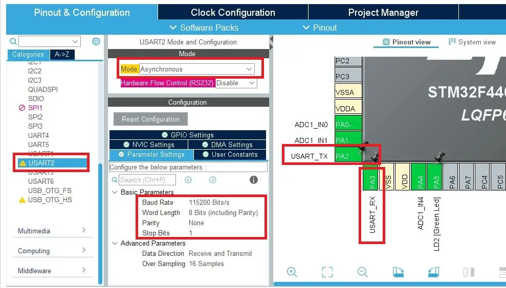
If the ADC Configuration is finished, then click on USART2 and Configure the peripheral. As we are using Nucleo-F446RE development board, STM32Cube IDE configure the USART2 peripheral by default for programming and debugging purpose.
Project Code and Description
main.c file of STM32CubeIDE
// Includes
#include "main.h"
#include "stdio.h"
#include "stdint.h"

// Private variables
 ADC_HandleTypeDef hadc1;
 DMA_HandleTypeDef hdma_adc1;
 UART_HandleTypeDef huart2;

// Private function prototypes
void SystemClock_Config(void);
static void MX_GPIO_Init(void);
static void MX_DMA_Init(void);
static void MX_USART2_UART_Init(void);
static void MX_ADC1_Init(void);

// This array hold the the channels ADC value
volatile uint16_t adc_dma_result[3];
// This variable calculate the array length.
// In our case, array size in 3
int adc_channel_count = sizeof(adc_dma_result)/sizeof(adc_dma_result[0]);
// This flag will help to detect
// the DMA conversion completed or not
uint8_t adc_conv_complete_flag = 0;

// This character buffer array will
// store the result after conversion complete
char dma_result_buffer[100];

/**
  * @brief  The application entry point.
  * @retval int
  */
int main(void)
{
  // Reset of all peripherals, Initializes the Flash interface and the Systick.
  HAL_Init();

  /* Configure the system clock */
  SystemClock_Config();

  /* Initialize all configured peripherals */
  MX_GPIO_Init();
  MX_DMA_Init();
  MX_USART2_UART_Init();
  MX_ADC1_Init();

  // Initialize the DMA conversion
  HAL_ADC_Start_DMA(&hadc1, (uint32_t *) adc_dma_result , adc_channel_count);

  /* Infinite loop */
  while (1)
  {
       // when adc_conv_complete_flag is set to 1,
       // that means DMA conversion is completed
       if(adc_conv_complete_flag == 1){
	  // this snprintf function helps to convert the adc_dma_result array
	  // into string and store in dma_result_buffer character array
	  snprintf(dma_result_buffer, 100, "CH_1: %d, CH_2: %d, CH_3: %d\r\n", adc_dma_result[0], adc_dma_result[1], adc_dma_result[2]);
	  // we just send the dma_result_buffer character array with ADC values
	  // to our computer serial terminal software (Tera Term) using UART peripheral of STM32
	  HAL_UART_Transmit(&huart2, (uint8_t *) dma_result_buffer, sizeof(dma_result_buffer), HAL_MAX_DELAY);
	  // adc_conv_complete_flag variable is set to 0, because,
         // we alert this flag variable for new DMA conversion completion
	 adc_conv_complete_flag = 0;
        // delay for 500 Milliseconds
        HAL_Delay(500);
     }
  }
}

// when DMA conversion is completed, HAL_ADC_ConvCpltCallback function
// will interrupt the processor. You can find this function in
// Drivers>STM32F4xx_HAL_Drivers>stm32f4xx_hal_adc.c file as __weak attribute
void HAL_ADC_ConvCpltCallback(ADC_HandleTypeDef* hadc){
	// I set adc_conv_complete_flag variable to 1 when,
	// HAL_ADC_ConvCpltCallback function is call.
	adc_conv_complete_flag = 1;
}

/**
  * @brief System Clock Configuration
  * @retval None
  */
void SystemClock_Config(void)
{
  RCC_OscInitTypeDef RCC_OscInitStruct = {0};
  RCC_ClkInitTypeDef RCC_ClkInitStruct = {0};

  /** Configure the main internal regulator output voltage
  */
  __HAL_RCC_PWR_CLK_ENABLE();
  __HAL_PWR_VOLTAGESCALING_CONFIG(PWR_REGULATOR_VOLTAGE_SCALE1);

  /** Initializes the RCC Oscillators according to the specified parameters
  * in the RCC_OscInitTypeDef structure.
  */
  RCC_OscInitStruct.OscillatorType = RCC_OSCILLATORTYPE_HSE;
  RCC_OscInitStruct.HSEState = RCC_HSE_ON;
  RCC_OscInitStruct.PLL.PLLState = RCC_PLL_ON;
  RCC_OscInitStruct.PLL.PLLSource = RCC_PLLSOURCE_HSE;
  RCC_OscInitStruct.PLL.PLLM = 4;
  RCC_OscInitStruct.PLL.PLLN = 180;
  RCC_OscInitStruct.PLL.PLLP = RCC_PLLP_DIV2;
  RCC_OscInitStruct.PLL.PLLQ = 2;
  RCC_OscInitStruct.PLL.PLLR = 2;
  if (HAL_RCC_OscConfig(&RCC_OscInitStruct) != HAL_OK)
  {
    Error_Handler();
  }

  /** Activate the Over-Drive mode
  */
  if (HAL_PWREx_EnableOverDrive() != HAL_OK)
  {
    Error_Handler();
  }

  /** Initializes the CPU, AHB and APB buses clocks
  */
  RCC_ClkInitStruct.ClockType = RCC_CLOCKTYPE_HCLK|RCC_CLOCKTYPE_SYSCLK
                              |RCC_CLOCKTYPE_PCLK1|RCC_CLOCKTYPE_PCLK2;
  RCC_ClkInitStruct.SYSCLKSource = RCC_SYSCLKSOURCE_PLLCLK;
  RCC_ClkInitStruct.AHBCLKDivider = RCC_SYSCLK_DIV1;
  RCC_ClkInitStruct.APB1CLKDivider = RCC_HCLK_DIV4;
  RCC_ClkInitStruct.APB2CLKDivider = RCC_HCLK_DIV2;

  if (HAL_RCC_ClockConfig(&RCC_ClkInitStruct, FLASH_LATENCY_5) != HAL_OK)
  {
    Error_Handler();
  }
}

/**
  * @brief ADC1 Initialization Function
  * @param None
  * @retval None
  */
static void MX_ADC1_Init(void)
{
  ADC_ChannelConfTypeDef sConfig = {0};

  /** Configure the global features of the ADC (Clock, Resolution, Data Alignment and number of conversion)
  */
  hadc1.Instance = ADC1;
  hadc1.Init.ClockPrescaler = ADC_CLOCK_SYNC_PCLK_DIV4;
  hadc1.Init.Resolution = ADC_RESOLUTION_12B;
  hadc1.Init.ScanConvMode = ENABLE;
  hadc1.Init.ContinuousConvMode = ENABLE;
  hadc1.Init.DiscontinuousConvMode = DISABLE;
  hadc1.Init.ExternalTrigConvEdge = ADC_EXTERNALTRIGCONVEDGE_NONE;
  hadc1.Init.ExternalTrigConv = ADC_SOFTWARE_START;
  hadc1.Init.DataAlign = ADC_DATAALIGN_RIGHT;
  hadc1.Init.NbrOfConversion = 3;
  hadc1.Init.DMAContinuousRequests = ENABLE;
  hadc1.Init.EOCSelection = ADC_EOC_SINGLE_CONV;
  if (HAL_ADC_Init(&hadc1) != HAL_OK)
  {
    Error_Handler();
  }

  /** Configure for the selected ADC regular channel its corresponding rank in the sequencer and its sample time.
  */
  sConfig.Channel = ADC_CHANNEL_0;
  sConfig.Rank = 1;
  sConfig.SamplingTime = ADC_SAMPLETIME_3CYCLES;
  if (HAL_ADC_ConfigChannel(&hadc1, &sConfig) != HAL_OK)
  {
    Error_Handler();
  }

  /** Configure for the selected ADC regular channel its corresponding rank in the sequencer and its sample time.
  */
  sConfig.Channel = ADC_CHANNEL_1;
  sConfig.Rank = 2;
  if (HAL_ADC_ConfigChannel(&hadc1, &sConfig) != HAL_OK)
  {
    Error_Handler();
  }

  /** Configure for the selected ADC regular channel its corresponding rank in the sequencer and its sample time.
  */
  sConfig.Channel = ADC_CHANNEL_4;
  sConfig.Rank = 3;
  if (HAL_ADC_ConfigChannel(&hadc1, &sConfig) != HAL_OK)
  {
    Error_Handler();
  }
}

/**
  * @brief USART2 Initialization Function
  * @param None
  * @retval None
  */
static void MX_USART2_UART_Init(void)
{
  /* USER CODE END USART2_Init 1 */
  huart2.Instance = USART2;
  huart2.Init.BaudRate = 115200;
  huart2.Init.WordLength = UART_WORDLENGTH_8B;
  huart2.Init.StopBits = UART_STOPBITS_1;
  huart2.Init.Parity = UART_PARITY_NONE;
  huart2.Init.Mode = UART_MODE_TX_RX;
  huart2.Init.HwFlowCtl = UART_HWCONTROL_NONE;
  huart2.Init.OverSampling = UART_OVERSAMPLING_16;
  if (HAL_UART_Init(&huart2) != HAL_OK)
  {
    Error_Handler();
  }
}

/**
  * Enable DMA controller clock
  */
static void MX_DMA_Init(void)
{

  /* DMA controller clock enable */
  __HAL_RCC_DMA2_CLK_ENABLE();

  /* DMA interrupt init */
  /* DMA2_Stream0_IRQn interrupt configuration */
  HAL_NVIC_SetPriority(DMA2_Stream0_IRQn, 0, 0);
  HAL_NVIC_EnableIRQ(DMA2_Stream0_IRQn);

}

/**
  * @brief GPIO Initialization Function
  * @param None
  * @retval None
  */
static void MX_GPIO_Init(void)
{
  GPIO_InitTypeDef GPIO_InitStruct = {0};

  /* GPIO Ports Clock Enable */
  __HAL_RCC_GPIOC_CLK_ENABLE();
  __HAL_RCC_GPIOH_CLK_ENABLE();
  __HAL_RCC_GPIOA_CLK_ENABLE();
  __HAL_RCC_GPIOB_CLK_ENABLE();

  /*Configure GPIO pin Output Level */
  HAL_GPIO_WritePin(LD2_GPIO_Port, LD2_Pin, GPIO_PIN_RESET);

  /*Configure GPIO pin : B1_Pin */
  GPIO_InitStruct.Pin = B1_Pin;
  GPIO_InitStruct.Mode = GPIO_MODE_IT_FALLING;
  GPIO_InitStruct.Pull = GPIO_NOPULL;
  HAL_GPIO_Init(B1_GPIO_Port, &GPIO_InitStruct);

  /*Configure GPIO pin : LD2_Pin */
  GPIO_InitStruct.Pin = LD2_Pin;
  GPIO_InitStruct.Mode = GPIO_MODE_OUTPUT_PP;
  GPIO_InitStruct.Pull = GPIO_NOPULL;
  GPIO_InitStruct.Speed = GPIO_SPEED_FREQ_LOW;
  HAL_GPIO_Init(LD2_GPIO_Port, &GPIO_InitStruct);

}

/* USER CODE BEGIN 4 */

/* USER CODE END 4 */

/**
  * @brief  This function is executed in case of error occurrence.
  * @retval None
  */
void Error_Handler(void)
{
  /* USER CODE BEGIN Error_Handler_Debug */
  /* User can add his own implementation to report the HAL error return state */
  __disable_irq();
  while (1)
  {
  }
  /* USER CODE END Error_Handler_Debug */
}

#ifdef  USE_FULL_ASSERT
/**
  * @brief  Reports the name of the source file and the source line number
  *         where the assert_param error has occurred.
  * @param  file: pointer to the source file name
  * @param  line: assert_param error line source number
  * @retval None
  */
void assert_failed(uint8_t *file, uint32_t line)
{
  /* USER CODE BEGIN 6 */
  /* User can add his own implementation to report the file name and line number,
     ex: printf("Wrong parameters value: file %s on line %d\r\n", file, line) */
  /* USER CODE END 6 */
}
#endif /* USE_FULL_ASSERT */
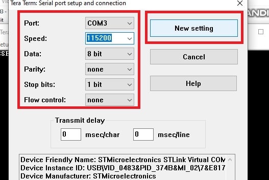
Output of the Code
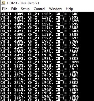
As we mentioned earlier, we are using Tera Term Serial Terminal Software to communicate with STM32 Microcontroller using USART. It is an open source and free software. You can download the software from here. After downloading, go to Setup > Serial Port and select the PORT where the Microcontroller is connected. Also, select Boud rate (Speed), in our case we select the Speed of 115200 for our Nucleo development board. After configuring all the parameters, click on New Setting and open the Serial Monitor window where you can see the output.