
In this tutorial, we will interface STM32 with a 16×2 LCD module by using I2C based PCF8574 I/O expender. Also, we will build an example project using STM32 NUCLEO-F446RE development board in STM32CubeIDE that will print some text and integer value to the LCD module. So, let’s get started.
Our other STM32 related tutorials are:
- How to create a project in stm32CubeMX for Keil uvision Ide
- How to create stm32 project in stm32cubeide with example code
- Getting Started with FreeRTOS in STM32
- Stm32 I2C communication with HAL code example
- STM32 ADC Interfacing with HAL code example
- STM32 ADC tutorial using DMA with HAL Code Example
Introduction
Interfacing LCD modules with microcontrollers is a common requirement in many embedded applications. LCDs provide an easy-to-read visual output that can display various types of information, such as sensor readings, status messages, and user inputs. However, traditional methods of interfacing LCDs with microcontrollers can be complex, requiring many GPIO pins and complex wiring.
This is where I2C comes in. I2C is a communication protocol that allows multiple devices to communicate with each other using just two wires: a clock line (SCL) and a data line (SDA). I2C is a popular choice for interfacing LCD modules with microcontrollers because it requires only two pins, simplifying the wiring and reducing the number of GPIO pins needed.
In this tutorial, we will discuss how to interface an STM32 microcontroller with an I2C LCD module. The LCD module we will use is a Hitachi HD44780 controller based 16×2 LCD module with a PCF8574 I2C interface. We will use the STM32CubeIDE software to write the code, which provides a comprehensive set of tools for developing, debugging, and deploying STM32-based embedded applications.
16×2 LCD Display
The Hitachi HD44780 is a popular LCD controller used in many 16×2 character LCD displays. This controller is widely used due to its low power consumption, ease of use, and reliability. The HD44780 supports up to 32 characters (16 columns x 2 rows) and offers various features such as character generation, display data RAM, and display on/off control. This LCD controller communicates with microcontrollers through an 8-bit parallel interface or a 4-bit parallel interface, depending on the mode selected. The HD44780 is widely used in various applications, such as industrial control systems, consumer electronics, and automotive displays.
Features of the 16×2 LCD Display
- Low power consumption
- 16×2 character display (16 columns x 2 rows)
- Supports up to 32 characters
- Supports alphanumeric characters and symbols
- Built-in character RAM for up to 8 user-defined characters
- 8-bit parallel interface or 4-bit parallel interface
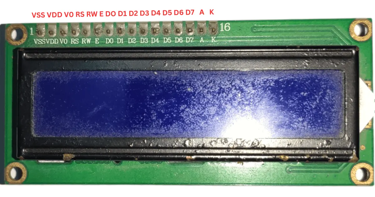
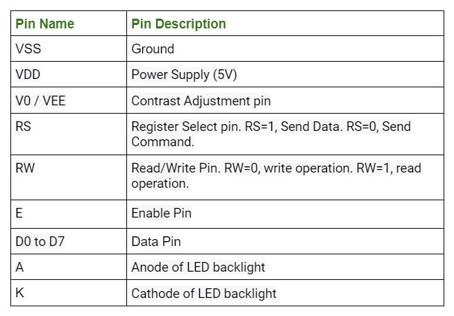
16×2 LCD Pinout and Pin Description
PCF8574 I/O Expender
The PCF8574 is an 8-bit I/O expander that communicates with microcontrollers through the I2C protocol. It is commonly used to expand the number of GPIO pins available to the microcontroller. The PCF8574 can be used to interface with various peripherals, including LCD displays, LEDs, and sensors. It has eight I/O pins that can be used for both input and output operations. The PCF8574 is also designed to work at low voltage levels, making it suitable for battery-powered applications. Additionally, multiple PCF8574 devices can be connected together, providing an easy way to expand the number of I/O pins even further. Overall, the PCF8574 is a versatile and cost-effective solution for expanding the number of I/O pins available to a microcontroller.
Features of the PCF8574
- 8-bit remote I/O expander for the I2C-bus
- 8 programmable I/O pins that can be used for both input and output operations
- Compatible with I2C interfaces operating at up to 400 kHz
- Wide supply voltage range of 2.5 V to 6 V
- Low standby current consumption, making it ideal for battery-powered applications
- Internal power-on reset
- Addressable via three hardware address pins, allowing up to eight devices to be connected to the same I2C bus
- Suitable for various applications, including industrial control systems, home automation, and consumer electronics.
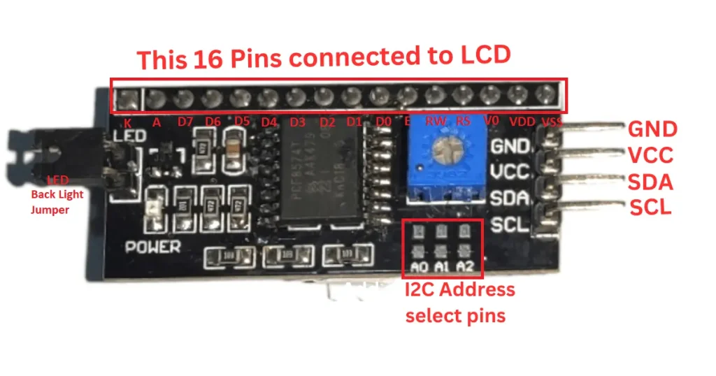
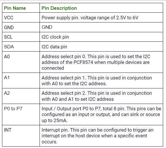
PCF8574 Pinout and Pin Description
Interfacing STM32 with I2C LCD (The Project)
In this section of the tutorial, we will build a real world project by using LCD I2C display. We will display some character, string and integer to the LCD display. We connect the display with STM32 by using only 4 wires (Vcc, Ground, SDA and SCL) through PCF8574 module.
Component List for the Project
[wptb id=935]
For troubleshooting, some extremely useful test equipment
[wptb id=890]
Affiliate Disclosure: When you click on links to make a purchase, this can result in this website earning a commission. Affiliate programs and affiliations include, but are not limited to Amazon.com
Circuit Diagram
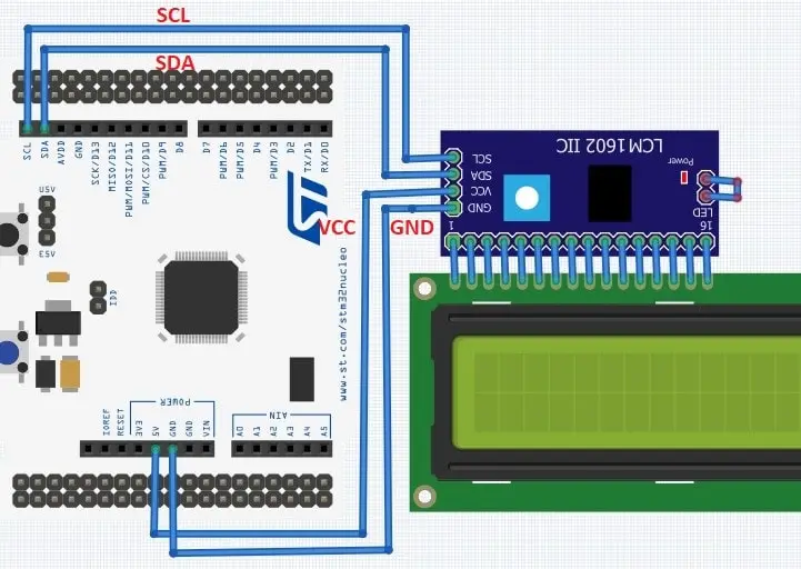
Circuit Connection Description
Connection between LCD and PCF8574
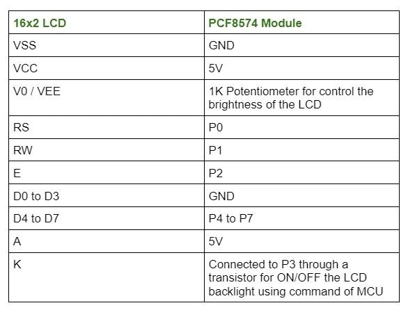
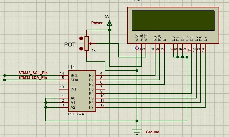
Internal Circuit diagram between LCD and PCF8574
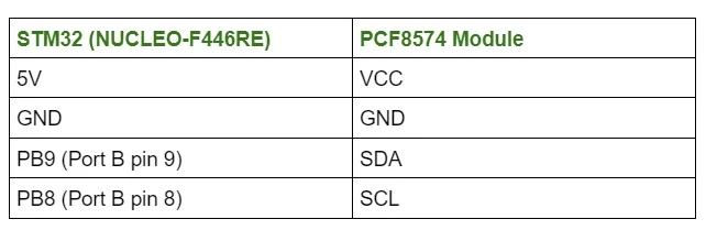
Connection between STM32 and PCF8574
Preparing STM32Cube IDE for the project
For project creation in Stm32CubeIDE, please visit your previous tutorial. Link is given below,
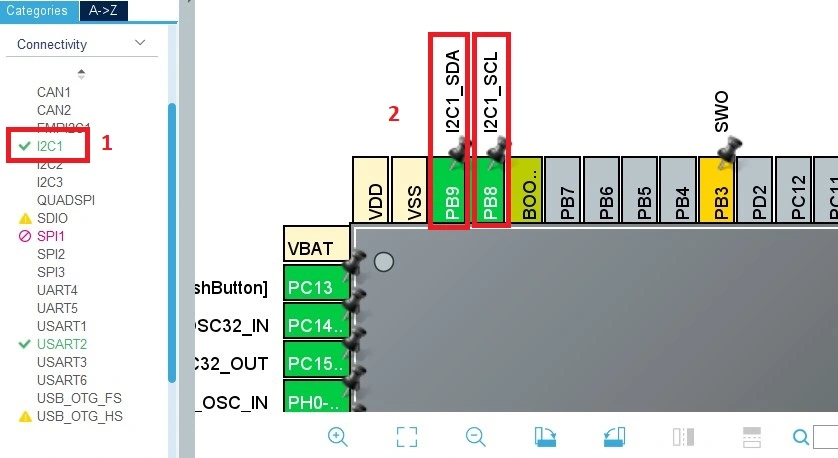
After creating the project in Stm32CubeIDE, Enable the I2C1 peripheral from the device configuration tools of Stm32CubeIDE. The SCL and SDA pins are GPIO B pin 8 (PB8) and GPIO B pin 9 (GPIO9) respectably.
Project Code and Description
In this section, we will write some code that will print some text and number to the LCD monitor.
Code description
First, we need to define the I2C address PCF8574, pin numbers that is connected between LCD and PCF8574. Also, define the LCD rows and columns
#define I2C_ADDR 0x27 // I2C address of the PCF8574
#define RS_BIT 0 // Register select bit
#define EN_BIT 2 // Enable bit
#define BL_BIT 3 // Backlight bit
#define D4_BIT 4 // Data 4 bit
#define D5_BIT 5 // Data 5 bit
#define D6_BIT 6 // Data 6 bit
#define D7_BIT 7 // Data 7 bit

#define LCD_ROWS 2 // Number of rows on the LCD
#define LCD_COLS 16 // Number of columns on the LCD
lcd_write_nibble() function sends a 4-bit nibble of data to the LCD display through the PCF8574 I2C I/O expander.
void lcd_write_nibble(uint8_t nibble, uint8_t rs) {
  uint8_t data = nibble << D4_BIT;
  data |= rs << RS_BIT;
  data |= backlight_state << BL_BIT; // Include backlight state in data
  data |= 1 << EN_BIT;
  HAL_I2C_Master_Transmit(&hi2c1, I2C_ADDR << 1, &data, 1, 100);
  HAL_Delay(1);
  data &= ~(1 << EN_BIT);
  HAL_I2C_Master_Transmit(&hi2c1, I2C_ADDR << 1, &data, 1, 100);
}
lcd_send_cmd() function sends a command to the LCD display through the PCF8574 I2C I/O expander.
void lcd_send_cmd(uint8_t cmd) {
  uint8_t upper_nibble = cmd >> 4;
  uint8_t lower_nibble = cmd & 0x0F;
  lcd_write_nibble(upper_nibble, 0);
  lcd_write_nibble(lower_nibble, 0);
  if (cmd == 0x01 || cmd == 0x02) {
    HAL_Delay(2);
  }
}
lcd_send_data() function sends data to the LCD display through the PCF8574 I2C I/O expander.
void lcd_send_data(uint8_t data) {
  uint8_t upper_nibble = data >> 4;
  uint8_t lower_nibble = data & 0x0F;
  lcd_write_nibble(upper_nibble, 1);
  lcd_write_nibble(lower_nibble, 1);
}
lcd_init() function initializes the LCD display.
void lcd_init() {
  HAL_Delay(50);
  lcd_write_nibble(0x03, 0);
  HAL_Delay(5);
  lcd_write_nibble(0x03, 0);
  HAL_Delay(1);
  lcd_write_nibble(0x03, 0);
  HAL_Delay(1);
  lcd_write_nibble(0x02, 0);
  lcd_send_cmd(0x28);
  lcd_send_cmd(0x0C);
  lcd_send_cmd(0x06);
  lcd_send_cmd(0x01);
  HAL_Delay(2);
}
lcd_write_string() function writes a null-terminated string to the LCD display through the PCF8574 I2C I/O expander.
void lcd_write_string(char *str) {
  while (*str) {
    lcd_send_data(*str++);
  }
}
lcd_set_cursor() function sets the cursor position on the LCD display
void lcd_set_cursor(uint8_t row, uint8_t column) {
    uint8_t address;
    switch (row) {
        case 0:
            address = 0x00;
            break;
        case 1:
            address = 0x40;
            break;
        default:
            address = 0x00;
    }
    address += column;
    lcd_send_cmd(0x80 | address);
}
lcd_clear() function clears the display of the LCD.
void lcd_clear(void) {
	lcd_send_cmd(0x01);
    HAL_Delay(2);
}
lcd_backlight() function turns the backlight of the LCD on or off
void lcd_backlight(uint8_t state) {
  if (state) {
    backlight_state = 1;
  } else {
    backlight_state = 0;
  }
}
This is the main function of the program Calls MX_GPIO_Init(), MX_USART2_UART_Init(), and MX_I2C1_Init() to initialize the GPIO, USART2, and I2C1 peripherals, respectively. These functions are likely generated by STM32CubeIDE and set up the hardware to the desired configuration.
After that Calls lcd_init() to initialize the LCD display. also calls lcd_backlight(1) to turn on the backlight of the LCD.
In the while loop, we print “EmbeddedThere” text in the first row and count some integer number in the second row.
int main(void)
{
  /* Reset of all peripherals, Initializes the Flash interface and the Systick. */
  HAL_Init();

  /* Configure the system clock */
  SystemClock_Config();

  /* Initialize all configured peripherals */
  MX_GPIO_Init();
  MX_USART2_UART_Init();
  MX_I2C1_Init();
  lcd_init();
  lcd_backlight(1); // Turn on backlight

  char *text = "EmbeddedThere";
  char int_to_str[10];
  int count=0;

  while (1)
  {
	  sprintf(int_to_str, "%d", count);
	  lcd_clear();
	  lcd_set_cursor(0, 0);
	  lcd_write_string(text);
	  lcd_set_cursor(1, 0);
	  lcd_write_string(int_to_str);
	  count++;
	  memset(int_to_str, 0, sizeof(int_to_str));
	  HAL_Delay(1500);

  }
}
Full Code
/* Includes */
#include "main.h"
#include <stdio.h>
#include <string.h>

#define I2C_ADDR 0x27 // I2C address of the PCF8574
#define RS_BIT 0 // Register select bit
#define EN_BIT 2 // Enable bit
#define BL_BIT 3 // Backlight bit
#define D4_BIT 4 // Data 4 bit
#define D5_BIT 5 // Data 5 bit
#define D6_BIT 6 // Data 6 bit
#define D7_BIT 7 // Data 7 bit

#define LCD_ROWS 2 // Number of rows on the LCD
#define LCD_COLS 16 // Number of columns on the LCD

// Define global variable for backlight state
uint8_t backlight_state = 1;

/* Private variables */
 I2C_HandleTypeDef hi2c1;

UART_HandleTypeDef huart2;

/* Private function prototypes */
void SystemClock_Config(void);
static void MX_GPIO_Init(void);
static void MX_USART2_UART_Init(void);
static void MX_I2C1_Init(void);

void lcd_write_nibble(uint8_t nibble, uint8_t rs);
void lcd_send_cmd(uint8_t cmd);
void lcd_send_data(uint8_t data);
void lcd_init();
void lcd_write_string(char *str);
void lcd_set_cursor(uint8_t row, uint8_t column);
void lcd_clear(void);
void lcd_backlight(uint8_t state);

/**
  * @brief  The application entry point.
  * @retval int
  */
int main(void)
{
  /* Reset of all peripherals, Initializes the Flash interface and the Systick. */
  HAL_Init();

  /* Configure the system clock */
  SystemClock_Config();

  /* Initialize all configured peripherals */
  MX_GPIO_Init();
  MX_USART2_UART_Init();
  MX_I2C1_Init();
  lcd_init();
  lcd_backlight(1); // Turn on backlight

  char *text = "EmbeddedThere";
  char int_to_str[10];
  int count=0;

  while (1)
  {
	  sprintf(int_to_str, "%d", count);
	  lcd_clear();
	  lcd_set_cursor(0, 0);
	  lcd_write_string(text);
	  lcd_set_cursor(1, 0);
	  lcd_write_string(int_to_str);
	  count++;
	  memset(int_to_str, 0, sizeof(int_to_str));
	  HAL_Delay(1500);

  }
}

void lcd_write_nibble(uint8_t nibble, uint8_t rs) {
  uint8_t data = nibble << D4_BIT;
  data |= rs << RS_BIT;
  data |= backlight_state << BL_BIT; // Include backlight state in data
  data |= 1 << EN_BIT;
  HAL_I2C_Master_Transmit(&hi2c1, I2C_ADDR << 1, &data, 1, 100);
  HAL_Delay(1);
  data &= ~(1 << EN_BIT);
  HAL_I2C_Master_Transmit(&hi2c1, I2C_ADDR << 1, &data, 1, 100);
}

void lcd_send_cmd(uint8_t cmd) {
  uint8_t upper_nibble = cmd >> 4;
  uint8_t lower_nibble = cmd & 0x0F;
  lcd_write_nibble(upper_nibble, 0);
  lcd_write_nibble(lower_nibble, 0);
  if (cmd == 0x01 || cmd == 0x02) {
    HAL_Delay(2);
  }
}

void lcd_send_data(uint8_t data) {
  uint8_t upper_nibble = data >> 4;
  uint8_t lower_nibble = data & 0x0F;
  lcd_write_nibble(upper_nibble, 1);
  lcd_write_nibble(lower_nibble, 1);
}

void lcd_init() {
  HAL_Delay(50);
  lcd_write_nibble(0x03, 0);
  HAL_Delay(5);
  lcd_write_nibble(0x03, 0);
  HAL_Delay(1);
  lcd_write_nibble(0x03, 0);
  HAL_Delay(1);
  lcd_write_nibble(0x02, 0);
  lcd_send_cmd(0x28);
  lcd_send_cmd(0x0C);
  lcd_send_cmd(0x06);
  lcd_send_cmd(0x01);
  HAL_Delay(2);
}

void lcd_write_string(char *str) {
  while (*str) {
    lcd_send_data(*str++);
  }
}

void lcd_set_cursor(uint8_t row, uint8_t column) {
    uint8_t address;
    switch (row) {
        case 0:
            address = 0x00;
            break;
        case 1:
            address = 0x40;
            break;
        default:
            address = 0x00;
    }
    address += column;
    lcd_send_cmd(0x80 | address);
}

void lcd_clear(void) {
	lcd_send_cmd(0x01);
    HAL_Delay(2);
}

void lcd_backlight(uint8_t state) {
  if (state) {
    backlight_state = 1;
  } else {
    backlight_state = 0;
  }
}
Please Note: We have not included some parts of the code which are auto-generated by STM32CubeIDE.