
If you’re venturing into the world of embedded systems development, you’ll soon realize the importance of an efficient real-time operating system (RTOS) to manage tasks and resources effectively. One popular choice for RTOS implementation is FreeRTOS, a powerful and versatile open-source solution. In this tutorial, we’ll explore the fundamentals of RTOS and learn how to get started with FreeRTOS in STM32 Microcontroller. Along the way, we’ll also provide example code snippets to help you grasp the concepts more easily.
STM32 FreeRTOS tutorial series:
Our other STM32-related tutorials are:
- How to interface STM32 with RS485 (Modbus) sensors
- STM32 ADC Interfacing with HAL code example
- Interfacing STM32 with I2C LCD : HAL example code included
- Stm32 Bluetooth module HC-05 interfacing with HAL code example
- How to create a project in stm32CubeMX for Keil uvision Ide
- How to create stm32 project in stm32cubeide with example code
What is RTOS?
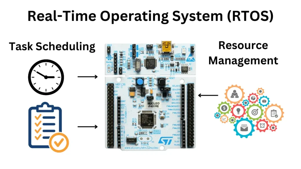
RTOS stands for Real-Time Operating System. It is a specialized operating system designed to handle real-time applications that have specific timing and responsiveness requirements. Unlike general-purpose operating systems (OS), an RTOS provides deterministic behavior, ensuring that tasks are executed within specific time constraints.
In an RTOS, tasks are scheduled and executed based on their priority and time requirements. It ensures that critical tasks receive the necessary processing time and resources to meet their timing deadlines. Real-time operating systems are commonly used in embedded systems, such as microcontrollers, where precise timing and responsiveness are crucial.
How RTOS works?
Let’s consider a real-world example to understand how an RTOS works. Imagine you have an autonomous robot that performs various tasks in a warehouse, such as picking up items and placing them in specific locations.
The robot’s tasks include:
- Sensor Reading: The robot needs to continuously read data from its sensors, such as distance sensors and cameras, to detect obstacles, recognize objects, and navigate the environment.
- Path Planning: Based on the sensor data, the robot needs to determine the optimal path to navigate through the warehouse, avoiding obstacles and reaching the desired locations efficiently.
- Object Detection: The robot needs to analyze the camera data to identify and classify objects in its surroundings, distinguishing between different items to be picked up or avoided.
- Motion Control: Once the path is planned and objects are detected, the robot needs to control its motors and actuators to move smoothly and precisely, following the planned trajectory and performing tasks like grasping objects.
In this scenario, an RTOS comes into play to manage the execution of these tasks efficiently and in a timely manner. Here’s how it works:
- Task Scheduling: The RTOS scheduler assigns priorities to each task based on their importance and time constraints. For example, the sensor reading task may have a higher priority to ensure real-time obstacle detection, while path planning can have a lower priority.
- Context Switching: The RTOS handles context switching, which means it can pause the execution of one task and switch to another task seamlessly. This allows the robot to respond quickly to changing situations and events.
- Resource Management: The RTOS manages the sharing of resources among tasks. For instance, if multiple tasks need to access the robot’s motors simultaneously, the RTOS ensures that they can do so without conflicts by implementing synchronization mechanisms like semaphores or mutexes. We will discuss semaphores and mutexes in the next tutorials.
- Timeliness: The RTOS guarantees that critical tasks are executed within their specified deadlines. For example, the motion control task needs to execute with precise timing to ensure the robot moves accurately and avoids collisions.
By utilizing an RTOS, the robot can effectively handle multiple tasks concurrently, respond to sensor inputs in real time, and achieve reliable and deterministic behavior. The RTOS ensures that each task receives the necessary processing time and resources to fulfill its requirements, ultimately enabling the smooth and efficient operation of the autonomous robot in the warehouse environment.
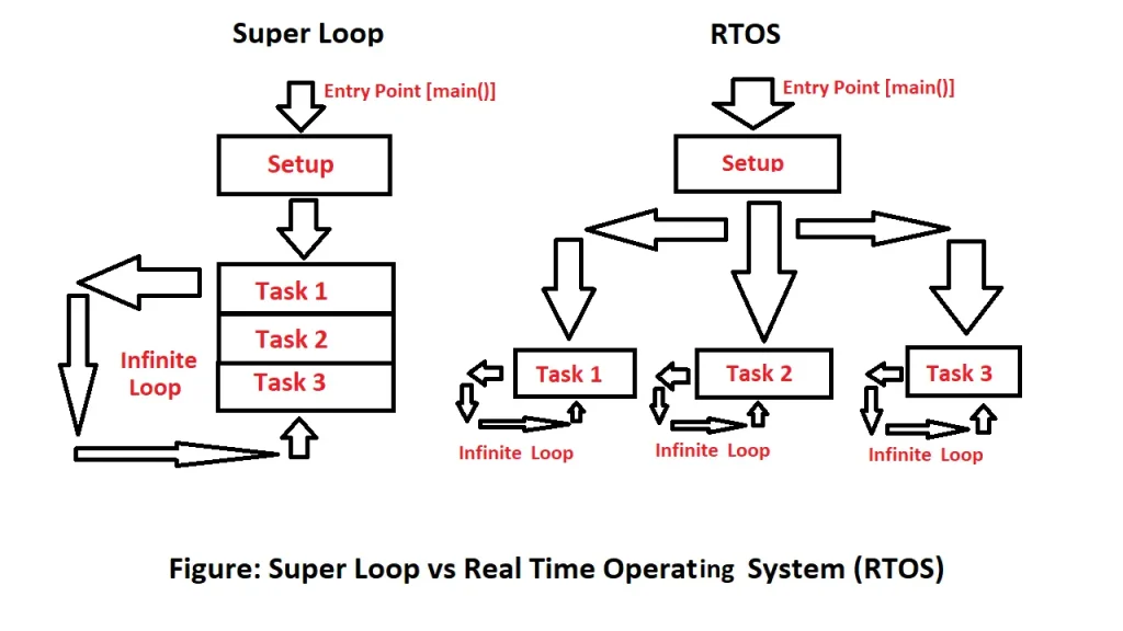
Difference between super loop architecture and RTOS in Microcontroller
When it comes to designing microcontroller-based systems, there are two common approaches for handling tasks and resources: super loop architecture and Real-Time Operating System (RTOS). Both have their advantages and drawbacks, and the choice between them depends on the specific application requirements and constraints.
Super loop architecture, also known as the main loop architecture, is a simple and straightforward approach for handling tasks in microcontroller-based systems. In this architecture, the main program loop repeatedly executes a sequence of tasks, each of which takes a fixed amount of time to complete. The tasks are scheduled sequentially, and the order of execution is typically determined by the order in which they appear in the main loop.
RTOS, on the other hand, is a more advanced and flexible approach for handling tasks and resources in microcontroller-based systems. In RTOS, the tasks are managed by a kernel, which is responsible for scheduling, context switching, and resource allocation. Each task has its own priority and execution time, and the kernel ensures that high-priority tasks are executed before low-priority ones.
What is FreeRTOS?
FreeRTOS, which stands for Free Real-Time Operating System, is an open-source real-time operating system kernel designed specifically for embedded systems. It provides a compact and efficient solution for running multiple tasks concurrently while meeting strict timing requirements.
Developed by Richard Barry in 2003, FreeRTOS offers a preemptive multitasking environment, where tasks are scheduled and executed based on their priorities. It allows developers to break down complex applications into smaller tasks, each with its own priority and execution requirements.
FreeRTOS supports a wide range of microcontrollers and microprocessors, including the popular STM32 family. It offers features such as task management, inter-task communication, synchronization mechanisms, timers, and memory management.
Tasks in FreeRTOS are created and managed using APIs provided by the kernel. Each task has its own stack and can perform specific operations independently. The kernel scheduler determines which task should run based on their priorities and any synchronization or timing constraints.
FreeRTOS also provides synchronization mechanisms like semaphores, mutexes, and queues, which allow tasks to communicate and share resources safely. This ensures coordinated execution and avoids conflicts between tasks.
One of the key advantages of FreeRTOS is its small footprint. It has a minimal memory overhead, making it suitable for resource-constrained embedded systems. Additionally, it is well-documented, actively maintained, and has a large user community, providing ample resources and support for developers.
To read more about FreeRTOS, you can visit their official website.
How to setup FreeRTOS in STM32 Microcontroller
In this section of the tutorial, we will show how to set up the FreeRTOS project in the STM32 NUCLEO–F446RE Development board using STM32Cube IDE and build a real-world example project by using two LEDs that will blink at different speeds according to task priority. We can use any STM32 microcontroller for this project, just set up the project according to your MCU in STM32CubeIDE.
FreeRTOS vs. CMSIS-RTOS
Before setup the FreeRTOS in STM32, we need to understand the integration of FreeRTOS within STM32CubeIDE is crucial. Although FreeRTOS serves as a foundational software framework, handling task switching and scheduling, it’s noteworthy that we won’t be directly invoking FreeRTOS functions.
To enhance code portability across different ARM processors, ARM has developed the CMSIS-RTOS library. This library enables us to make function calls to the underlying RTOS, streamlining the process and ensuring compatibility with a wide range of ARM processors. This image describes how ARM’s CMSIS libraries interact with third-party software:
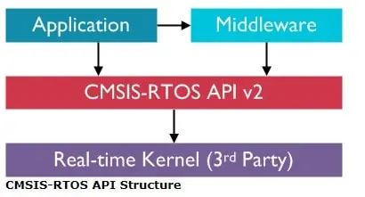
FreeRTOS is our RTOS Kernel. We will be making calls to CMSIS-RTOS (version 2) in order to control the underlying FreeRTOS.
Required Hardware for the project
| Component Name | Quantity | Purchase Link |
|---|---|---|
| STM32 Nucleo Dev. Board | 1 | Amazon |
| LED | 2 | Amazon |
| Resistor (330 ohm) | 2 | Amazon |
| Jumper Wire Pack | 1 | Amazon |
| Breadboard | 1 | Amazon |
| USB Mini-B cable | 1 | Amazon |
For troubleshooting, some extremely useful test equipment
| Equipment Name | Purchase Link |
|---|---|
| Best Oscilloscope for Professionals | Amazon |
| Best Oscilloscope for Beginners and Students | Amazon |
| Logic Analyzer | Amazon |
| Best Budget Multimeter | Amazon |
| Adjustable Bench Power Supply | Amazon |
Affiliate Disclosure: When you click on links to make a purchase, this can result in this website earning a commission. Affiliate programs and affiliations include, but are not limited to Amazon.com
Circuit Diagram
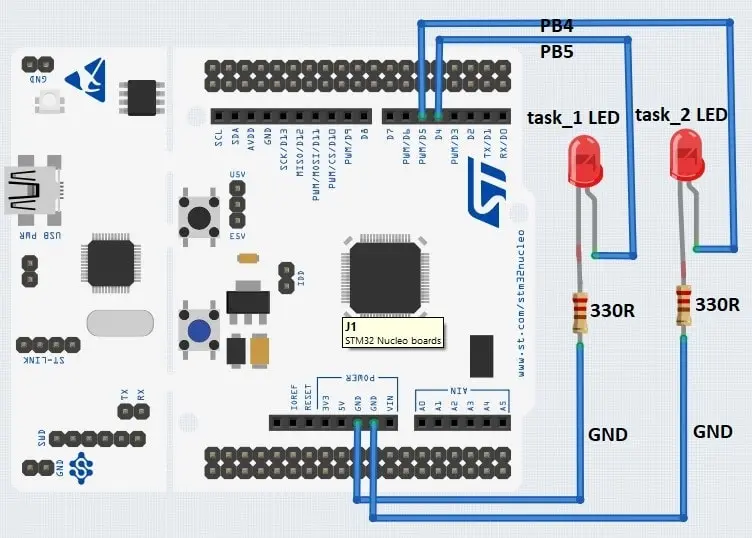
Circuit Connections
| STM32 Nucleo Dev. Board | LED Pin |
|---|---|
| GPIO B Pin 4 (PB4 / D5) | task_1 LED (Anode pin) |
| GPIO B Pin 5 (PB5 / D4) | task_2 LED (cathode pin) |
| Ground | task_1 and task_2 LED Cathode pin |
Creating a FreeRTOS project in STM32CubeIDE
For project creation in Stm32Cube IDE, please visit your previous tutorial. The link is given below:
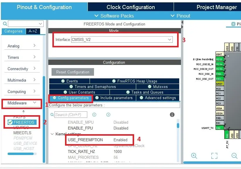
After creating the project in Stm32CubeIDE, it will open the default page for you called Device Configuration Tools. In Device Configuration Tools go to Categories > Middleware > FREERTOS. Under the Mode Selection Dropdown menu, select Interface to CMSIS_V2. Then select the Config parameters tab and go to Kernel settings and Enable USE_PREEMPTION. We Enable the Preemption because We will use Preemption based scheduling in which higher priority tasks can take control from the lower ones.
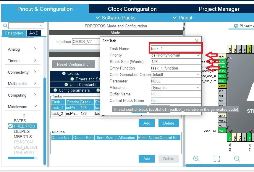
After that, go to the Tasks and Queues tab and Here you will see the predefined task called defaultTask, we will rename the task as task_1. You can also change the Priority, Stack Size, and Entry Function parameters of the task. We will select Priority as osPriorityNornal, Stack Size (Words) to 128.
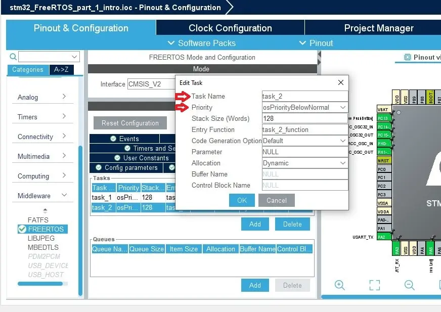
After editing the first tasks, we will create another task called task_2 and we change the Priority of this task to osPriorityBelowNormal this means task_1 will have a higher priority than the task_2 because we selected task_1 priority as osPriorityNornal.
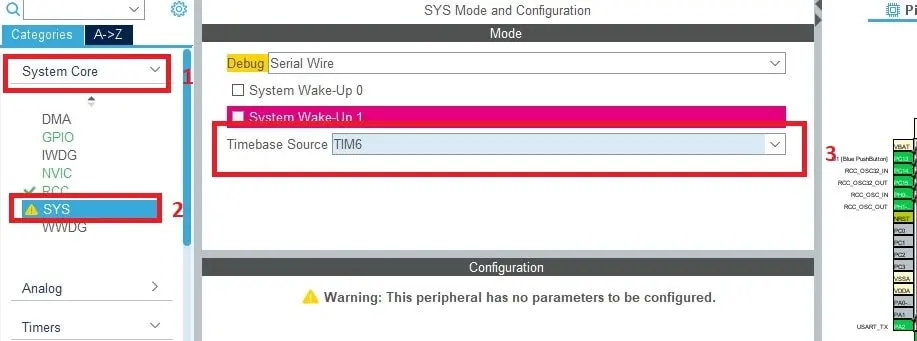
After configuring the tasks, go to System Core > Sys and Select the Timebase Source to TIM6 (Timer 6) because the SysTick timer is a specialized feature found in most ARM processors, serving primarily for operating system tasks. In the context of STM32 microcontrollers, the default configuration sets SysTick to generate an interrupt every 1 millisecond.
When using the STM32 HAL (Hardware Abstraction Layer), SysTick is automatically utilized for functions like HAL_Delay() and HAL_GetTick(). Consequently, the STM32 HAL framework assigns a high priority to SysTick. However, FreeRTOS needs SysTick for its scheduler as a result, it requires SysTick to be a much lower priority.
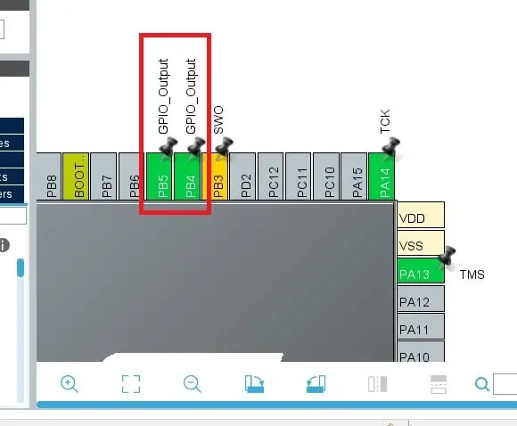
After completing all the FreeRTOS stuff, we will configure two GPIO Pin PB4 and PB5 as output to demonstrate the FreeRTOS tasks.
Finally, save the project and generate the code as all the configurations are completed.
Project Code and Description
To illustrate the concepts of FreeRTOS so far, let’s implement a simple example project using two tasks created earlier in STM32Cube IDE for the STM32 Nucleo board. This example will demonstrate the creation of a task that blinks LEDs at regular intervals. We will provide the necessary code snippets along with detailed explanations to help you understand the implementation.
After finishing the code generation, before the main function, you should see the two threads being defined where we give each thread a name, priority, and stack size which are autogenerated by the STM32Cube IDE.
/* Definitions for task_1 */
osThreadId_t task_1Handle;
const osThreadAttr_t task_1_attributes = {
  .name = "task_1",
  .stack_size = 128 * 4,
  .priority = (osPriority_t) osPriorityNormal,
};
/* Definitions for task_2 */
osThreadId_t task_2Handle;
const osThreadAttr_t task_2_attributes = {
  .name = "task_2",
  .stack_size = 128 * 4,
  .priority = (osPriority_t) osPriorityBelowNormal,
};
After that, you can see CubeIDE automatically defines the entry functions for us as task_1_function and task_2_function. Entry functions are the functions where we will write our code in an infinite loop.
void task_1_function(void *argument);
void task_2_function(void *argument);
In the main function, you should see kernel will initialize by using osKernelInitialize function.
/* Init scheduler */
  osKernelInitialize();
After initializing the kernel if we scroll down, we will see that our entry functions are passed to osThreadNew function with the attributes.
/* Create the thread(s) */
  /* creation of task_1 */
  task_1Handle = osThreadNew(task_1_function, NULL, &task_1_attributes);

  /* creation of task_2 */
  task_2Handle = osThreadNew(task_2_function, NULL, &task_2_attributes);
Finally our FreeRTOS scheduler will start by calling the osKernelStart function. At this point, FreeRTOS take control of the system, and the osKernelStart function never exit. After the osKernelStart function, you don’t want to write any code past it including in the while(1) loop.
/* Start scheduler */
  osKernelStart();
After the main function scroll down and find our two entry functions called task_1_function and task_2_function where we write our LED blinking code. The code is very simple, we just blink the two LEDs in the for loop using a 500ms delay. We use osDelay function instead of HAL_Delay because osDelay is a non-blocking CMSIS RTOS function. osDelay allows the schedular to run the other tasks while we wait for the current task.
Please Note that entry functions are not return anything and they are running a forever loop unless the thread is terminated.
Task 1 entry function
/* USER CODE END Header_task_1_function */
void task_1_function(void *argument)
{
  /* USER CODE BEGIN 5 */
  /* Infinite loop */
  for(;;)
  {
	HAL_GPIO_TogglePin(GPIOB, GPIO_PIN_4);
        osDelay(500);
  }
  /* USER CODE END 5 */
}
Task 2 entry function
/* USER CODE END Header_task_2_function */
void task_2_function(void *argument)
{
  /* USER CODE BEGIN task_2_function */
  /* Infinite loop */
  for(;;)
  {
	HAL_GPIO_TogglePin(GPIOB, GPIO_PIN_5);
    osDelay(250);
  }
  /* USER CODE END task_2_function */
}
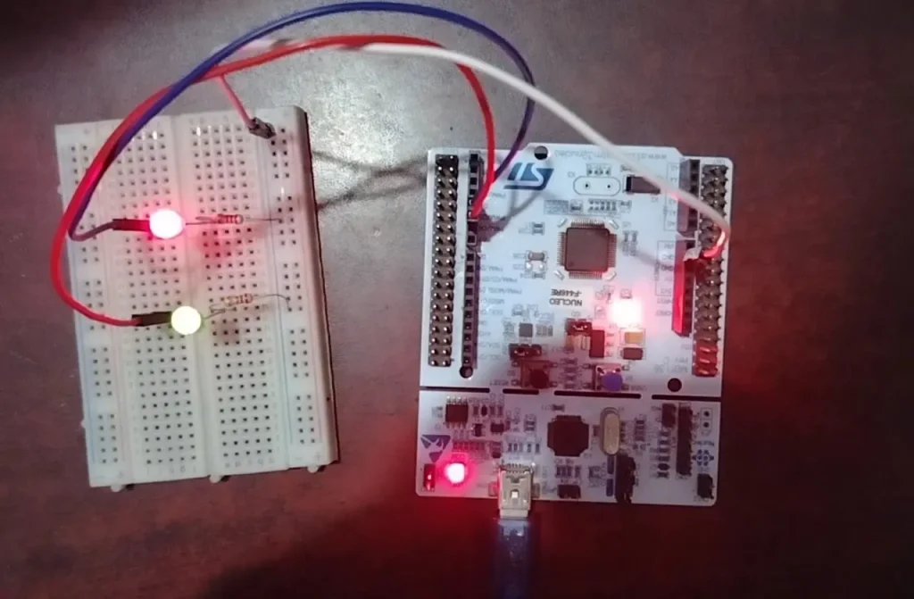
Testing and Deployment
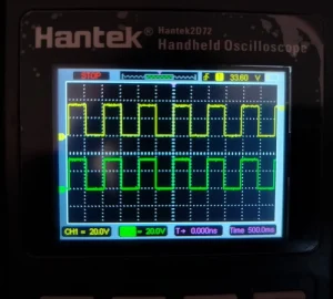
Once the code is uploaded to the microcontroller, you should see that the two LEDs are blink at the same frequency because at first, task_1 LED is ON and it goes to sleep for 500 milliseconds while scheduler executes the task_2 entry function and it will turn ON the task_2 LED at the same time and go to sleep to 500 milliseconds. After 500 milliseconds both LEDs will be turned OFF at the same time. In this pattern, the tasks are switched one after another while the higher priority task will execute first then the lower one.
If you connect a Oscilloscope to PB4 and PB5 pin of STM32 Nucleo board respect to ground, you will see the same webform for both the pins because both the task will run at the same time. Remember, we toggle the PB4 pin in our task_1 and PB5 pin in task_2 with 500 millisecond delay.
Full Source Code
main.c file
/* USER CODE END Header */
/* Includes */
#include "main.h"
#include "cmsis_os.h"

/* Private variables */
 UART_HandleTypeDef huart2;

/* Definitions for task_1 */
osThreadId_t task_1Handle;
const osThreadAttr_t task_1_attributes = {
  .name = "task_1",
  .stack_size = 128 * 4,
  .priority = (osPriority_t) osPriorityNormal,
};
/* Definitions for task_2 */
osThreadId_t task_2Handle;
const osThreadAttr_t task_2_attributes = {
  .name = "task_2",
  .stack_size = 128 * 4,
  .priority = (osPriority_t) osPriorityBelowNormal,
};

/* Private function prototypes */
void SystemClock_Config(void);
static void MX_GPIO_Init(void);
static void MX_USART2_UART_Init(void);
void task_1_function(void *argument);
void task_2_function(void *argument);

/**
  * @brief  The application entry point.
  * @retval int
  */
int main(void)
{
  /* USER CODE BEGIN 1 */

  /* USER CODE END 1 */

  /* MCU Configuration*/

  /* Reset of all peripherals, Initializes the Flash interface and the Systick. */
  HAL_Init();

  /* Configure the system clock */
  SystemClock_Config();

  /* Initialize all configured peripherals */
  MX_GPIO_Init();
  MX_USART2_UART_Init();

  /* Init scheduler */
  osKernelInitialize();

  /* Create the thread(s) */
  /* creation of task_1 */
  task_1Handle = osThreadNew(task_1_function, NULL, &task_1_attributes);

  /* creation of task_2 */
  task_2Handle = osThreadNew(task_2_function, NULL, &task_2_attributes);

  /* Start scheduler */
  osKernelStart();

  /* We should never get here as control is now taken by the scheduler */
  /* Infinite loop */
  /* USER CODE BEGIN WHILE */
  while (1)
  {
    /* USER CODE END WHILE */

    /* USER CODE BEGIN 3 */
  }
  /* USER CODE END 3 */
}

/* USER CODE BEGIN Header_task_1_function */
/**
  * @brief  Function implementing the task_1 thread.
  * @param  argument: Not used
  * @retval None
  */
/* USER CODE END Header_task_1_function */
void task_1_function(void *argument)
{
  /* USER CODE BEGIN 5 */
  /* Infinite loop */
  for(;;)
  {
	HAL_GPIO_TogglePin(GPIOB, GPIO_PIN_4);
        osDelay(500);
  }
  /* USER CODE END 5 */
}

/* USER CODE BEGIN Header_task_2_function */
/**
* @brief Function implementing the task_2 thread.
* @param argument: Not used
* @retval None
*/
/* USER CODE END Header_task_2_function */
void task_2_function(void *argument)
{
  /* USER CODE BEGIN task_2_function */
  /* Infinite loop */
  for(;;)
  {
	HAL_GPIO_TogglePin(GPIOB, GPIO_PIN_5);
        osDelay(250);
  }
  /* USER CODE END task_2_function */
}
Please Note: Certain portions of the code, specifically those automatically generated by STM32CubeIDE, have been omitted.