In this tutorial, we will explain the basic principles of UART/USART and the Direct Memory Access (DMA) of the STM32 microcontroller. To get you started, we will show you how to interface STM32 UART peripherals using DMA in STM32 Nucleo development Board and STM32Cube IDE.
You may also like reading:
Our other STM32-related tutorials are:
- How to interface STM32 with RS485 (Modbus) sensors with HAL example code
- STM32 PWM Tutorial
- STM32 Timer tutorial using interrupt
STM32 UART/USART peripheral overview
The STM32 microcontroller family from STMicroelectronics includes a versatile UART (Universal Asynchronous Receiver/Transmitter) or USART (Universal Synchronous Asynchronous Receiver/Transmitter) peripheral that allows serial communication with external devices and Sensors. UART and USART are commonly used to interface with various communication protocols like RS-232, RS-485, and others, as well as for general-purpose asynchronous and synchronous serial communication.
Here’s an overview of the key features and functionality of the STM32 UART/USART peripheral:
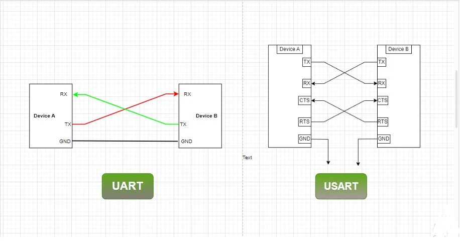
- UART vs. USART: UART (Universal Asynchronous Receiver/Transmitter) is for asynchronous communication. USART (Universal Synchronous Asynchronous Receiver/Transmitter) supports both asynchronous and synchronous communication, making it more versatile.
- Baud Rate: The baud rate determines the speed of data transmission and reception. STM32 UART/USART peripherals support programmable baud rates to match the communication speed of the connected devices.
- Data Frame Configuration: You can configure data frame parameters, including data bits (7, 8, or 9 bits), stop bits (1 or 2 bits), and parity (even, odd, or no parity).
- Synchronous Mode (USART only): USART supports synchronous mode where data is sent and received with a clock signal for precise synchronization with the connected device.
- Hardware Flow Control (USART only): USART peripherals often support hardware flow control mechanisms like CTS (Clear to Send) and RTS (Request to Send) pins for controlling data flow between devices.
- Buffering: STM32 UART/USART peripherals typically have built-in transmit and receive buffers to efficiently manage data transmission and reception.
- Interrupts and DMA: You can configure interrupts to trigger when specific events occur, such as data received or data transmitted. DMA (Direct Memory Access) can be used for more efficient data transfers without CPU intervention.
- Half-Duplex and Full-Duplex: UART/USART can operate in half-duplex (transmit or receive) or full-duplex (simultaneous transmit and receive) modes.
- Error Handling: These peripherals have error detection and correction mechanisms, including framing error, parity error, and noise error detection.
DMA in STM32 Microcontroller
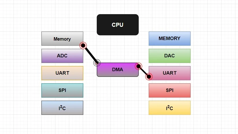
DMA stands for Direct Memory Access. DMA is a feature available in many microcontrollers, including those in the ARM-based STM32 series. This feature is used for efficient data transfer between peripherals and memory without the active involvement of the CPU.
The DMA controller acts as a bridge between the peripherals and the memory, enabling direct data transfers. Instead of the CPU being responsible for moving data between peripherals and memory, the DMA controller takes over this task, freeing up the CPU to perform other tasks.
The DMA controller operates independently and can transfer data in various modes, such as single, circular, or burst. It can transfer data to or from peripherals, memory, or even between different memory locations.
Using DMA can greatly enhance the performance of a microcontroller, especially in scenarios where frequent and high-speed data transfers are required, such as audio processing from ADC, data logging, or communication protocols like UART, SPI, or I2C.
STM32 UART peripheral interfacing using DMA: The Project
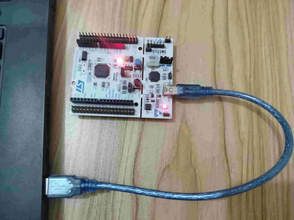
In this section of the tutorial, we will explore the STM32 UART peripheral in DMA mode. We will connect our STM32 Microcontroller to a Computer and receive data from the Computer serial terminal software (Tera Term) by using the UART DMA controller without interrupting the processor. We will transfer the received data back to the Serial Terminal by using the UART Polling Mode of STM32.
Component List
Some extremely useful test equipment for troubleshooting electronic circuit
| Equipment Name | Purchase Link |
|---|---|
| Best Oscilloscope for Professionals | Amazon |
| Best Oscilloscope for Beginners and Students | Amazon |
| Best Budget Multimeter | Amazon |
| Adjustable Bench Power Supply | Amazon |
Affiliate Disclosure: When you click on links to make a purchase, this can result in this website earning a commission. Affiliate programs and affiliations include, but are not limited to Amazon.com
Preparing STM32Cube IDE for the project
For project creation in Stm32CubeIDE, please visit your previous tutorial. Link is given below:
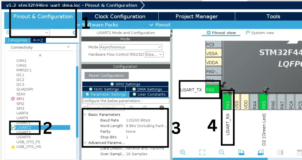
After creating the project in Stm32CubeIDE, Enable the USART2 peripheral from the device configuration tools of Stm32CubeIDE. For, USART2 we configure GPIO A pin 2 (PA2) as Tx, GPIO A pin 3 (PA3) as Rx.
After enabling USART2, click on USART2 Parameters Settings and configure the following parameters:
- Select the Baud Rate of 115200
- Word Length 8 Bits
- Parity: None
- Stop Bits: 1
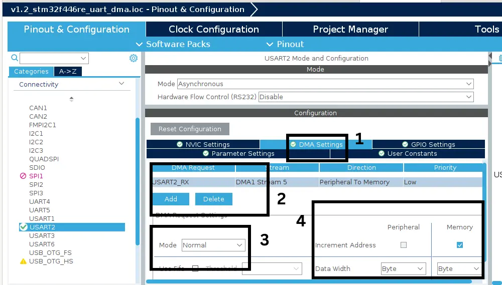
Next, click on DMA Settings and select DMA Request as USART2_RX. Go to DMA Request Settings and select the Normal Mode for DMA Request. Also, the data direction should be marked as Peripheral to Memory.
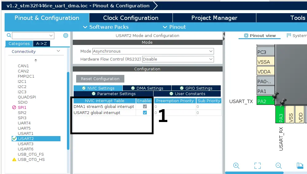
After completing the DMA settings, go to NVIC Interrupt Table tab and enable the USART2 global interrupt.
Project Code and Description
#define RxBuffer_Size 20
#define TxBuffer_Size 20
uint8_t RxBuffer[RxBuffer_Size];
uint8_t TxBuffer[TxBuffer_Size];
RxBuffer array will hold the data when UART DMA receives the data then TxBuffer array transmits back the data over UART.
HAL_UARTEx_ReceiveToIdle_DMA(&huart2, RxBuffer, RxBuffer_Size);
__HAL_DMA_DISABLE_IT(&hdma_usart2_rx, DMA_IT_HT);
AL_UARTEx_ReceiveToIdle_DMA function receives the data buffer in DMA mode. This HAL api function Receives an amount of data in DMA mode till either the expected number of data is received or an IDLE event occurs. IDLE event means there is no incoming data for some amount of time.
__HAL_DMA_DISABLE_IT function will disable the half transfer complete of data in DMA interrupt mode.
void HAL_UARTEx_RxEventCallback(UART_HandleTypeDef *huart, uint16_t Size){
	if(huart->Instance == USART2){
		len = strlen(RxBuffer);
		strncpy(TxBuffer,RxBuffer,len);
		HAL_UART_Transmit(&huart2,TxBuffer,len,HAL_MAX_DELAY); //transmit the full sentence again
		memset(TxBuffer, 0, sizeof(TxBuffer));
		memset(RxBuffer, 0, sizeof(RxBuffer));
		HAL_UARTEx_ReceiveToIdle_DMA(&huart2, RxBuffer, RxBuffer_Size);
		__HAL_DMA_DISABLE_IT(&hdma_usart2_rx, DMA_IT_HT);
	}
}
when DMA conversion is completed, HAL_UARTEx_RxEventCallback function will interrupt the processor. Inside the callback, we check if the callback is called by the USART2 peripheral or not. Then we copy the received data to the RxBuffer character array and send it back to the computer serial terminal by using HAL_UART_Transmit HAL API function. And again initiate the UART Receive DMA for the next conversion.
You can find all the functions in Drivers>STM32F4xx_HAL_Drivers>stm32f4xx_hal_uart.c location.
Full Code
/* Includes */
#include <stdint.h>
#include <string.h>
#include "main.h"

/* Private variables */
UART_HandleTypeDef huart2;
DMA_HandleTypeDef hdma_usart2_rx;

/* Private function prototypes */
void SystemClock_Config(void);
static void MX_GPIO_Init(void);
static void MX_DMA_Init(void);
static void MX_USART2_UART_Init(void);

/* Private user code -*/
/* USER CODE BEGIN 0 */
int len = 0;
#define RxBuffer_Size 20
#define TxBuffer_Size 20

uint8_t RxBuffer[RxBuffer_Size];
uint8_t TxBuffer[TxBuffer_Size];
/* USER CODE END 0 */

/**
  * @brief  The application entry point.
  * @retval int
  */
int main(void)
{
  /* USER CODE BEGIN 1 */

  /* USER CODE END 1 */

  /* MCU Configuration*/

  /* Reset of all peripherals, Initializes the Flash interface and the Systick. */
  HAL_Init();

  /* USER CODE BEGIN Init */

  /* USER CODE END Init */

  /* Configure the system clock */
  SystemClock_Config();

  /* USER CODE BEGIN SysInit */

  /* USER CODE END SysInit */

  /* Initialize all configured peripherals */
  MX_GPIO_Init();
  MX_DMA_Init();
  MX_USART2_UART_Init();
  /* USER CODE BEGIN 2 */
  // Initialize the DMA conversion
  HAL_UARTEx_ReceiveToIdle_DMA(&huart2, RxBuffer, RxBuffer_Size);
  __HAL_DMA_DISABLE_IT(&hdma_usart2_rx, DMA_IT_HT);
  /* USER CODE END 2 */

  /* Infinite loop */
  /* USER CODE BEGIN WHILE */
  while (1)
  {
    /* USER CODE END WHILE */

    /* USER CODE BEGIN 3 */
  }
  /* USER CODE END 3 */
}

// when DMA conversion is completed, HAL_ADC_ConvCpltCallback function
// will interrupt the processor.
void HAL_UARTEx_RxEventCallback(UART_HandleTypeDef *huart, uint16_t Size){
	// check if the callback is called by the USART2 peripheral
	if(huart->Instance == USART2){
		// take length of the RxBuffer
		len = strlen(RxBuffer);
		// Copy RxBuffer to TxBuffer
		strncpy(TxBuffer,RxBuffer,len);
		// Transmit the TxBuffer data over uart
		HAL_UART_Transmit(&huart2,TxBuffer,len,HAL_MAX_DELAY);
		// empty the TxBuffer and RxBuffer buffer
		memset(TxBuffer, 0, sizeof(TxBuffer));
		memset(RxBuffer, 0, sizeof(RxBuffer));
		// Initialize the DMA conversion
		HAL_UARTEx_ReceiveToIdle_DMA(&huart2, RxBuffer, RxBuffer_Size);
		__HAL_DMA_DISABLE_IT(&hdma_usart2_rx, DMA_IT_HT);
	}
}
Please Note: Certain portions of the code, specifically those automatically generated by STM32CubeIDE, have been omitted.
Output of the Code
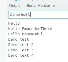
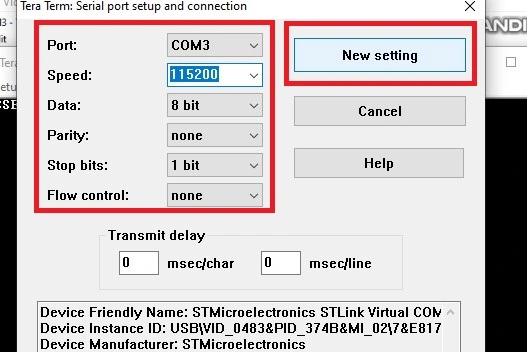
As we mentioned earlier, we are using Tera Term Serial Terminal Software for windows operating system to communicate with STM32 Microcontroller using USART. It is an open source and free software. You can download the software from here. After downloading, go to Setup > Serial Port and select the PORT where the Microcontroller is connected. Also, select Boud rate (Speed), in our case we select the Speed of 115200 for our Nucleo development board. After configuring all the parameters, click on New Setting and open the Serial Monitor window where you can see the output.