
In this tutorial, we will explain the basic principles of Inter-Integrated Circuit (I2C) communication and also closer look at the I2C hardware of the PIC microcontroller. To get you started, we will show you how to interface an OLED Display sensor with the PIC16F877A microcontroller using I2C protocol.
Our other PIC Microcontroller related tutorials are:
- Password based Door Lock System
- PIC Microcontroller Timer with example code
- How to generate PWM signal using PIC Microcontroller
Understanding I2C Communication
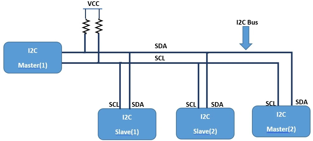
I2C (Inter-Integrated Circuit) is a popular synchronous serial communication protocol that allows multiple devices to communicate with each other over a short distance using only two bidirectional lines: Serial Data Line (SDA) and Serial Clock Line (SCL). The SDA line is used for data transfer, while the SCL line synchronizes the data transfer between the devices.
I2C follows a master-slave architecture, where one device acts as the master, controlling the communication, and the other devices are slaves. It was developed by Philips (now NXP Semiconductors) and is commonly used to connect various peripherals such as sensors, EEPROMs, LCD displays, and other digital ICs to microcontrollers and microprocessors.
How I2C Works?
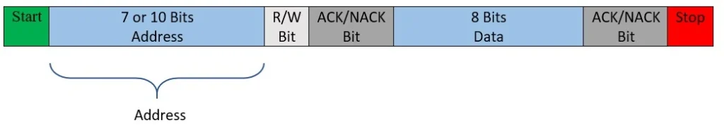
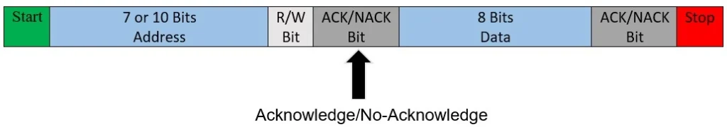
I2C data transfer is done in bytes. Each byte consists of 8 bits, including a 7-bit address and a data bit. The master initiates communication by sending a start condition, followed by the 7-bit address of the target slave device, and then the data to be transmitted. After each byte, the receiving device (either master or slave) sends an acknowledgment (ACK) or non-acknowledgment (NACK) signal to indicate successful or unsuccessful data reception, respectively.

Here are the key elements of I2C communication working:
Start Condition
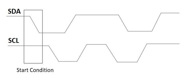
The Start Condition marks the beginning of a data transfer on the I2C bus. It is generated by the master device to initiate communication with a specific slave device. The Start Condition consists of the following sequence:
- The SDA line transitions from a high level (logic 1) to a low level (logic 0) while the SCL line is held high (logic 1).
- This sequence is often represented as a falling edge on the SDA line while SCL remains high.
Addressing
Each slave device on the I2C bus has a unique 7-bit or 10-bit address. The master specifies the target slave’s address when initiating communication, allowing it to communicate with a specific slave. For example, the address of the OLED display is 0X7C which we will use in our project.
Data Format
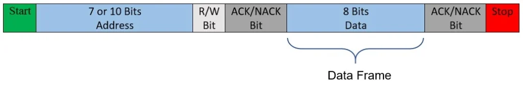
Data on the I2C bus is transmitted in 8-bit bytes, with the most significant bit (MSB) sent first.
Acknowledgments/Non-Acknowledgments
After transmitting 8 bits of data (a byte), the receiver (either the master or the slave) sends an acknowledgment (ACK) or non-acknowledgment (NACK) bit to indicate successful or unsuccessful data reception, respectively.
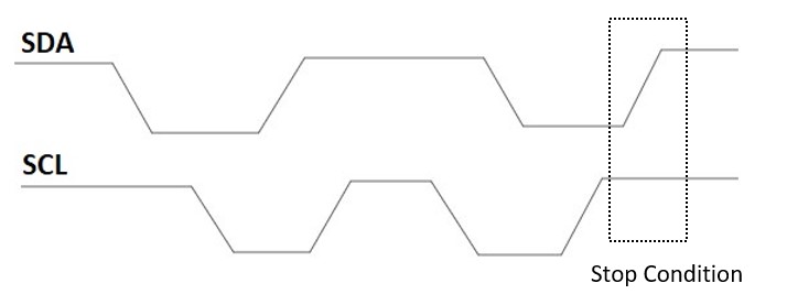
Stop Condition
The Stop Condition marks the end of a data transfer on the I2C bus. It is also generated by the master device and is used to release the bus and indicate that the communication is complete. The Stop Condition consists of the following sequence:
- The SDA line transitions from a low level (logic 0) to a high level (logic 1) while the SCL line is held high (logic 1).
- This sequence is often represented as a rising edge on the SDA line while SCL remains high.
Interfacing PIC Microcontroller with OLED Display using I2C: The Project
In this section, we will interfacing the PIC16F877A microcontroller with the OLED display using I2C communication protocol and display some text on the display module.
Configuring I2C peripheral in PIC Microcontroller
To enable I2C communication with the PIC16F877A, you need to configure its MSSP module. Here, are the steps to set up I2C communication:
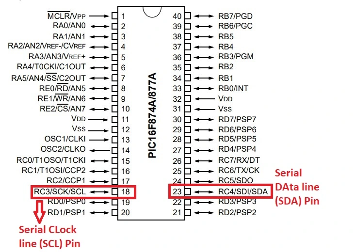
Step 1: Configure Pins
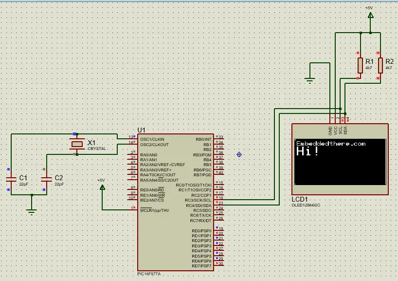
First, you need to configure the I/O pins for I2C communication. The SDA and SCL pins are usually mapped to specific pins on the PIC16F877A, such as RC4 and RC3, respectively. Configure these pins as inputs (TRISC3 = 1 and TRISC4 = 1).
Step 2: Set Up I2C Mode
The MSSP module can operate in either I2C Master mode or I2C Slave mode. In this case, we want the PIC16F877A to act as the I2C Master for controlling other I2C devices as Slave (e.g., OLED display). Set the MSSP module to I2C Master mode. We need to configure 6 registers for I2C communication. These are
- MSSP Control Register (SSPCON1)
- MSSP Control Register 2 (SSPCON2)
- MSSP Status Register (SSPSTAT)
- Serial Receive/Transmit Buffer Register (SSPBUF)
- MSSP Shift Register (SSPSR) – Not directly accessible
- MSSP Address Register (SSPADD)
SSPCON1 Register
The bit numbers 0 to 3(SSPM3:SSPM0) of the SSPCON1 register are used to select the mode for holding the slave address in slave mode and in the master mode it is used as the selection of clock speed mode. Bit number 5 is used for selection to enable or disable SDA and SCL pins.
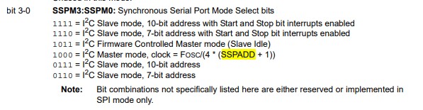
For example, SSPCON = 0b00101000; which means it is in master mode and the SDA and SCL pins are enabled.
SSPCON2 Register
These register is used for selecting start and stop condition. For example, SEN=1 (bit number 0 of SSPCON2 Register) means the start condition is enabled and PEN=1 means the stop condition is enabled.
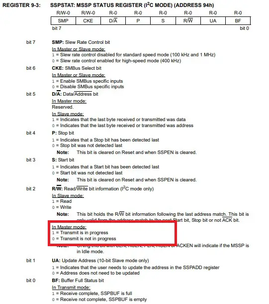
SSPSTAT Register
By configuring this register data can be read or written in slave mode. In master mode, the condition of data transmission is selected by this register. For example,if SSPSTAT= 0b00000100 then it is in master mode and the data Transmit is in progress.
SSPBUF Register
SSPBUF is the buffer register to which data bytes are written to or read from.
SSPADD Register
In I2C Slave mode, the SSPADD register is utilized to store the address of the slave device. When operating in Master mode, the lower seven bits of SSPADD function as the reload value for the baud rate generator.
Step 3: Configure Baud Rate
Set the baud rate for the I2C communication. The baud rate determines the speed at which data is transmitted between the master and slave devices.
When I2C mode is configured as a master, it is needs to define a data transfer rate or generate a baud rate. In master mode, only lower seven bits are used in MSSP Address Register (SSPADD). We can use this formula to calculate SSPADD value for the desired baud rate:
I2C_Freq = fOSC/4;
SSPADD  = (I2C_Freq/ Baud rate) -1;
Load this calculated value to MSSP Address (SSPADD) register. It defines the clock frequency for I2C peripheral.
Step 4: Initialize I2C
Once the necessary configurations are made, initialize the I2C communication by setting the appropriate registers and enabling the MSSP module.
The OLED Display (SSD-1306)
The SSD1306 is a popular OLED (Organic Light Emitting Diode) display module widely used in electronic projects and devices. It is known for its compact size, low power consumption, and impressive display quality. The SSD1306 supports various screen resolutions, making it suitable for displaying text, graphics, and even small images.
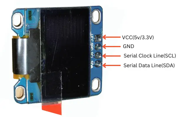
One of the key features of the SSD1306 is its ability to communicate using the I2C (Inter-Integrated Circuit) protocol. This simplifies the interfacing process, as it requires only two wires (SDA and SCL) for communication with the microcontroller.
OLED Display (SSD1306) Pin-Out
Component List for the Project
| Component Name | Quantity | Purchase Link |
|---|---|---|
| PIC Development Board | 1 | Amazon |
| OLED Display | 1 | Amazon |
| Breadboard | 1 | Amazon |
| Jumper Wire Pack | 1 | Amazon |
Affiliate Disclosure: When you click on links to make a purchase, this can result in this website earning a commission. Affiliate programs and affiliations include, but are not limited to Amazon.com
Connection Diagram between PIC16F877A and OLED Display
Creating The Project in MPLAB X IDE
Follow these steps to create a project for interfacing between PIC17F877A and SSD-1306 OLED display.
Step 1: Open your MPLAB X IDE and create a project.
Step 2: We will use our own library to make our project easier. Download the OLED display library zip file from GitHub.
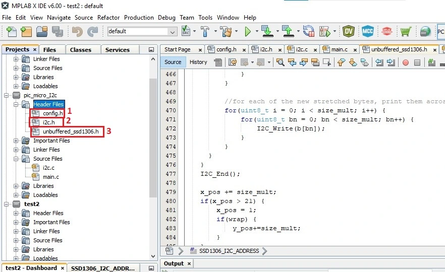
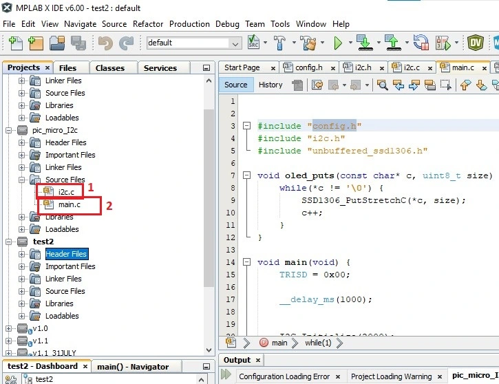
Step 3: After downloading you need to unzip this file and include these libraries in your project folder. To include header files, go to your project then go to Header Files>>Add Existing item>>select header file. Make sure you add all header files. After adding all header files it looks like.
Step 4: To include C files, go to your project then go to Source Files>>Add Existing item>>select i2c.c file.
Step 5: Save and build your project. After saving a HEX file will be created to your project folder.
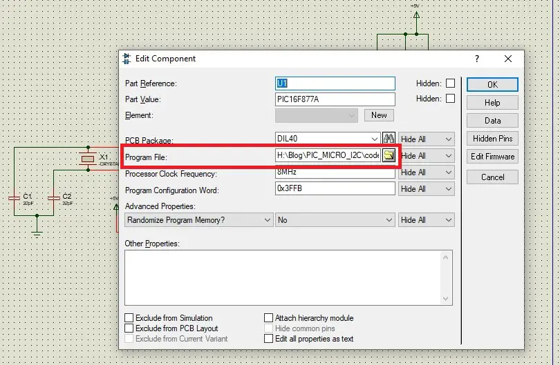
Step 6: To load hex file to the Proteus project, double-click on the PIC16F877A schematic and click program file icon and select your HEX file and click OK.
Code Explanation
I2C code is very complicated. So we discuss only the core section of the code. All I2C component has an address. You need to write address in the code. Go to unbuffered_ssd1306.h file and change the address to this line.
#define SSD1306_I2C_ADDRESS 0x78
In my case the address was 0x78. Your OLED display address maybe 0x3C or 0x78.
In while loop OLED display console position can be selected by SSD1306_GotoXY() function. For example, SSD1306_GotoXY(1,1) means the text will start from the first row and first column. If we want to write something with appropriate front size on OLED display then we can use oled_puts() function. For example, oled_puts(“Embeddedthere.com”, 1) means we will display Embeddedthere.com with front size 1. SSD1306_ClearDisplay() function clear the OLED display.
while(1) {
        PORTD ^= 0xFF;
        SSD1306_GotoXY(1,1);
        oled_puts("Embeddedthere.com", 1);
        SSD1306_GotoXY(1,2);
        oled_puts("Hi!", 2);
        __delay_ms(5000);
        SSD1306_ClearDisplay();
    }
Full Code
main.c file
#include "config.h"
#include "i2c.h"
#include "unbuffered_ssd1306.h"

void oled_puts(const char* c, uint8_t size) {
    while(*c != '\0') {
        SSD1306_PutStretchC(*c, size);
        c++;
    }
}

void main(void) {
    TRISD = 0x00;

    __delay_ms(1000);


    I2C_Initialize(2000);

    SSD1306_Init(SSD1306_SWITCHCAPVCC, SSD1306_I2C_ADDRESS);
    // clear the display
    SSD1306_ClearDisplay();


    while(1) {
        PORTD ^= 0xFF;

        SSD1306_GotoXY(1,1);
        oled_puts("Embeddedthere.com", 1);
        SSD1306_GotoXY(1,2);
        oled_puts("Hi!", 2);
        __delay_ms(5000);
        SSD1306_ClearDisplay();

    }

    return;
}