
ADC, or analog-to-digital converter, is used to read analog signals. For accurate reading, you have to have better knowledge about your microcontroller ADC and its features. In this tutorial, I am going to give a detailed explanation of the Raspberry Pi Pico ADC, and with a project, you will learn how you can read any analog value using the Raspberry Pi Pico ADC peripheral.
Our other Raspberry Pi Pico-related tutorials are:
- How to program Raspberry Pi Pico and Pico W using Arduino IDE
- How to interface Raspberry Pi Pico with RS485 Protocol
What is ADC?
An Analog-to-Digital Converter (ADC) is an essential component or method in electronics. It allows you to convert analog signals, such as voltage levels, into digital data that can be processed by a microcontroller.
Why do you need ADC?
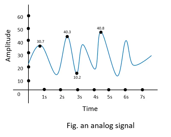
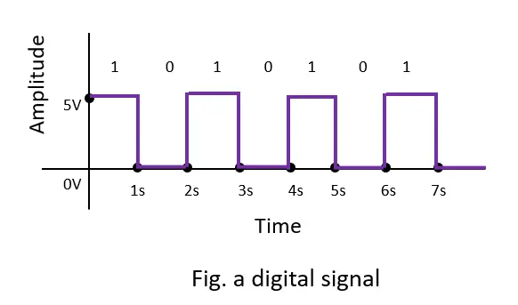
In the real world, almost everything is an analog signal. The sound, signal, and temperature are examples of analog signals. However, a microcontroller or microprocessor doesn’t understand analog signals. The microcontroller and microprocessor only understand digital signals 0s (0V) and 1s (5V). So, the analog-to-digital converter (ADC) does this job to read analog signals. Analog signals are continuous electrical signals that can vary in voltage or current over time, while digital data consists of discrete values, typically in the form of binary numbers (0s and 1s).
Suppose the Raspberry Pi Pico can handle input voltage in the range of 0 to 3.3V, and the ADC resolution is 12 bits. 12 bits means 2^12=4096, which means 0 to 3.3V is divided into 0 to 4095. Zero-volt (0V) represents the zero (0) ADC value, and 3.3V represents the 4095 ADC value. For example, if you get an analog value of 300 mV (0.3 volts), then the ADC value will be (4095*0.3)/3.3 = 372.
Raspberry Pi Pico ADC
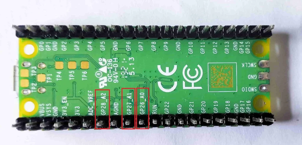
The Raspberry Pi Pico has three analog pins to read analog values from sensors. Although two other pins also support analog reading, they are not marked on the Pico board. One is used for measuring VSYS voltage, and the other is used for controlling the built-in temperature sensor. If you want to know more about Raspberry Pi Pico pinout then follow this article. A Complete Pinout Guide of Raspberry Pi Pico and Pico W: GPIOs Explanation.
| GPIO Pin | ADC channel | Function |
|---|---|---|
| GPIO26 | ADC0 | Used to read analog values from peripherals (12-bit resolution) |
| GPIO27 | ADC1 | Used to read analog values from peripherals (12-bit resolution) |
| GPIO28 | ADC2 | Used to read analog values from peripherals (12-bit resolution) |
| GPIO29 | ADC3 | Used to measure VSYS voltage level (Not marked on board) |
| ADC4 | Used to control built-in temperature sensor (Not marked on board) |
A short note of Pico ADC
- 12-bit resolution. That means it can slice an analog signal to 0 to samples.
- The maximum sampling rate of the ADC is 500 ksps (kilo samples per second).
- It supports both internal and external reference voltages for flexibility.
- The ADC includes filters for noise reduction, ensuring accurate readings.
- Three accessible ADC channels (ADC0, ADC2, ADC2 or GPIO26, GPIO27, GPIO28) for peripherals.
- On board ADC reference voltage (3.3V) with filtering and ADC ground (AGND). So, you need not any eternal ADC reference voltage in your project.
Raspberry Pi Pico ADC Interfacing: The Project
Now I will show you an example project, and after that, you will be able to read ADC values from any sensor. In this project, our aim is to read the ADC value using a Raspberry Pi Pico from a LDR sensor. The ADC value will be shown on the serial monitor. Also, I made a small high-light and low-light detector system with the help of the ADC of the Pico.
What is LDR Sensor?
An LDR (Light Dependent Resistor) is a sensor that works based on its resistance changing with light levels. In the presence of more light, its resistance decreases, and in low light, it increases. This property allows it to detect changes in light and is used in applications like adjusting brightness in response to ambient light or sensing when it’s dark enough to turn on outdoor lights. So, we will connect LDR with a voltage divider. In this case we use 10K ohm resistor.
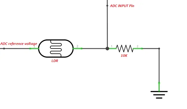
Circuit Diagram
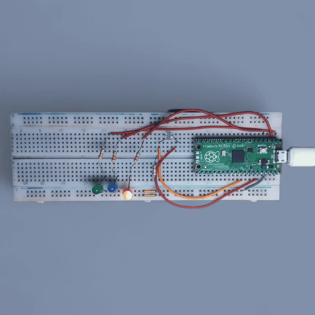
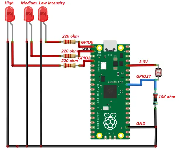
The complete circuit diagram is shown below.
Components List
| Component Name | Quantity | Purchase Link |
|---|---|---|
| Raspberry Pi Pico or Pico w | 1 | Amazon | Amazon |
| LDR sensor | 1 | Amazon |
| LED | 3 | Amazon |
| 10K and 220-ohm resistor | 1 | Amazon |
| Jumper wire Pack | 1 | Amazon |
Affiliate Disclosure: When you click on links to make a purchase, this can result in this website earning a commission. Affiliate programs and affiliations include, but are not limited to Amazon.com
Project Code and Description
#define LDR_Pin 27
#define LED1 0
#define LED2 1
#define LED3 2
Define GPIO 27 as LDR sensor reading, GPIO 0 as LOW light indication (LED1), GPIO 1 as MEDIUM light indication (LED2), and GPIO 2 as HIGH light indication (LED2). Remember, 27, 0, 1, and 2 are GPIO numbers, not pin numbers.
analogReadResolution(12);
In setup function set the ADC resolution as 12 bits. You can also choose 10 bit resolution by writing this line analogReadResolution(10);
pinMode(LDR_Pin,INPUT);
pinMode(LED1, OUTPUT);
pinMode(LED2, OUTPUT);
pinMode(LED3, OUTPUT);
Set the LDR GPIO number 27 as input for ADC and the other three GPIOs as output.
int adc_value = analogRead(LDR_Pin);
In the loop function, the analog value from the LDR sensor is read by the analogRead() function. This function also converts the analog value to a digital value. Finally, we store this ADC value as an integer number.
if (adc_value<200){
   Serial.println("Low Light Intensity");
   digitalWrite(LED1, HIGH);
   digitalWrite(LED2, LOW);
   digitalWrite(LED3, LOW);
 }
Now, using this ADC value, we will make a low, medium, and high light detector. To do this, we will meet three conditions.
The first condition is that if the ADC value is less than 200, then LED1 will be turned on and the other two LEDs will be turned off. Also, you will see a “Low Light Intensity” message on your serial monitor.
else if(adc_value>200 && adc_value<700){
   Serial.println("Medium Light Intensity");
   digitalWrite(LED1, LOW);
   digitalWrite(LED2, HIGH);
   digitalWrite(LED3, LOW);
 }
The second condition is that if the ADC value is greater than 200 and less than 700, then LED2 will turn on and LED1 and LED3 will turn off.
else if(adc_value>700){
   Serial.println("High Light Intensity");
   digitalWrite(LED1, LOW);
   digitalWrite(LED2, LOW);
   digitalWrite(LED3, HIGH);
 }
The third condition is that if the ADC value is greater than 700, then LED3 will turn on and LED1 and LED2 will turn off.
Full Code
#define LDR_Pin 27                  //define LDR sensor as GPIO 27 to read analog value
#define LED1 0                      //define Low light LED as GPIO 0
#define LED2 1                      //define medium light LED as GPIO 1
#define LED3 2                      //define High light LED as GPIO 2

void setup() {
  Serial.begin(9600);
  analogReadResolution(12);         //ADC resulation 12 bit. you can also take 10 bit using analogReadResolution(10); this line
  pinMode(LDR_Pin,INPUT);           //set LDR_Pin as input
  pinMode(LED1, OUTPUT);            //set LED1 as output
  pinMode(LED2, OUTPUT);            //set LED2 as output
  pinMode(LED3, OUTPUT);            //set LED3 as output


}

void loop() {
 int adc_value = analogRead(LDR_Pin);               //read the ADC value
 if (adc_value<200){                                //if adc_value<200 then turn on LED1 and turn off LED2 and LED3
   Serial.println("Low Light Intensity");           //you can also see this message on serial monitor
   digitalWrite(LED1, HIGH);
   digitalWrite(LED2, LOW);
   digitalWrite(LED3, LOW);
 }
 else if(adc_value>200 && adc_value<700){            //if adc_value>200 && adc_value<700 then turn on LED2 and turn off LED1 and LED3
   Serial.println("Medium Light Intensity");
   digitalWrite(LED1, LOW);
   digitalWrite(LED2, HIGH);
   digitalWrite(LED3, LOW);
 }
 else if(adc_value>700){
   Serial.println("High Light Intensity");          //if adc_value>700 then turn on LED2 and turn off LED1 and LED3
   digitalWrite(LED1, LOW);
   digitalWrite(LED2, LOW);
   digitalWrite(LED3, HIGH);
 }
 Serial.println(adc_value);                        //print the ADC value on serial monitor
 delay(500);                                       //take the adc value after every 500ms

}
Conclusion
This article helps you read analog values from any sensor using the Raspberry Pi Pico or Pico W. Also, you are able to make a low- and high-light-intensity detector system that may help you with another project.