In this tutorial, we will discuss how we can interface STM32 (as master) to any RS485 (Modbus RTU) based sensor (as slave) using STM32Cube IDE. We will create an example project by interfacing a RS485 (Modbus RTU) protocol based energy meter (PMC-220) using MAX485 (TTL to RS485 Converter) module and will collect voltage data (in Volt) from the energy meter.
You may also like reading:
- RS485 Communication Protocol: Basics, Working Principle & Application
- How to interface Modbus RTU (RS485) sensors with Arduino
- How to interface ESP32 with RS485 (Modbus) sensors
- Introduction to RS232 Serial Communication Protocol
- Multiple ESP32 Communication via RS485
- How to interface Arduino with RS485 (Modbus) protocol with example code
What is RS485?
RS-485, is a widely used communication protocol and physical layer standard in the field of serial data communication. It is known for its balanced differential signaling, which allows for reliable and robust data transmission over long distances up to 1,200 meter (4,000 ft), making it a popular choice in industrial and commercial applications.
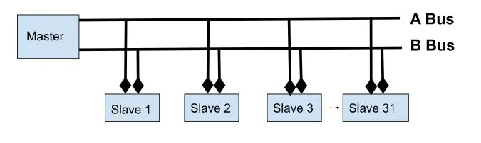
RS-485 supports multipoint communication, where multiple devices (up to 32 nodes or sensors) can be connected to a single communication bus, making it suitable for applications such as industrial automation, control systems, and data acquisition. Its ability to resist electromagnetic interference and noise makes RS-485 a dependable choice for ensuring stable and error-free data transfer in demanding environments.
How RS485 Works?
RS-485 operates using a balanced differential signaling scheme, where data is transmitted as voltage levels between two wires: one called “A” (positive) and the other “B” (negative). When a logical “1” is transmitted, wire A carries a higher voltage than wire B, and when a logical “0” is transmitted, wire B carries a higher voltage than wire A. This differential signaling method provides several advantages, including noise immunity and the ability to transmit data over long distances.
RS-485 devices are equipped with transceivers that convert between the logical voltage levels and the electrical signals on the communication lines. Multiple devices can be connected to the same RS-485 bus, and communication occurs in a half-duplex manner, where devices take turns transmitting and receiving data. To avoid data collisions, RS-485 uses a master-slave protocol in multiple-device setups, ensuring orderly data exchange within the network.
What is Modbus Protocol?
Modbus is a widely used communication protocol in the field of industrial automation and control systems. Developed in the late 1970s, it is a simple and open protocol that enables data exchange between devices such as programmable logic controllers (PLCs), sensors, and other automation components.
Modbus typically operates over serial communication Modbus RTU (Remote Terminal Unit) or Ethernet (Modbus TCP/IP), making it versatile and suitable for various applications. It uses a master-slave architecture, where a master device requests data or issues commands to one or more slave devices.
How Modbus Protocol Works?
Modbus operates on a simple and efficient request-response mechanism and typically works over serial (Modbus RTU) or Ethernet (Modbus TCP/IP) connections. Here’s how the Modbus protocol works:
- Master-Slave Architecture: Modbus follows a master-slave architecture. For example, if there is one master device (e.g., a programmable logic controller or SCADA system) that initiates communication with one or more slave devices (e.g., sensors, actuators, or other controllers). The master sends requests to read or write data, while the slaves respond to these requests.
- Function Codes: Modbus employs function codes to specify the type of operation to be performed. These function codes define read, write, and other operations, allowing for versatility in communication.
| Function Code | Description | Register Address Range |
|---|---|---|
| 01 | Read Coils (Discrete Inputs) | 00001 to 09999 (0-based addressing) |
| 02 | Read Discrete Inputs | 10001 to 19999 (0-based addressing) |
| 03 | Read Holding Registers | 40001 to 49999 (0-based addressing) |
| 04 | Read Input Registers | 30001 to 39999 (0-based addressing) |
| 05 | Write Single Coil | 00001 to 09999 (0-based addressing) |
| 06 | Write Single Register | 40001 to 49999 (0-based addressing) |
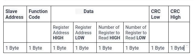
- Data Request: To retrieve data from a specific slave or instruct it to perform an action, the master sends a Modbus request message. This message includes the slave’s address, the type of request (e.g., read or write), the data address (memory location), and any necessary parameters.
| Field Name | Size (in Bytes) | Description |
|---|---|---|
| Slave Address | 1 | Address of the target slave device. |
| Function Code | 1 | Specifies the type of operation to perform. |
| Data | Variable | The data payload, the size varies depending on the unction code and operation. |
| CRC (Cyclic Redundancy Check) | 2 | A checksum used for error checking. |
For example, if we want to read data from Holding Register, the data request format might be like this:
- Slave Response: Upon receiving the request, the addressed slave processes it based on the request type and data address. If it’s a read request, the slave will respond with the requested data. If it’s a write request, the slave will perform the specified action and acknowledge the request.
| Field Name | Size (in Bytes) | Description |
|---|---|---|
| Slave Address | 1 | Address of the responding slave device. |
| Function Code | 1 | Echo of the function code from the request. |
| Byte Count | 1 | Number of bytes in the data field that follows. |
| Data | Variable | The data payload size varies by function code. |
| CRC (Checksum) | 2 | Cyclic Redundancy Check for error detection. |
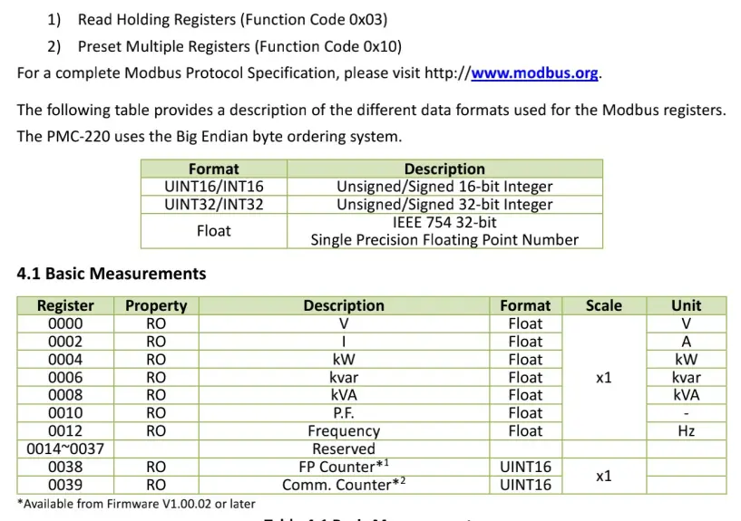
- Data Format: Modbus uses a structured data format to represent information, which typically includes integers, binary data, or floating-point values. The format varies depending on the data type and can be specified in the request.
- Error Checking: Modbus includes error-checking mechanisms like CRC (Cyclic Redundancy Check) to ensure data integrity during transmission. Both the master and slave devices use these checks to verify that the data received is error-free.
- Communication Modes: Modbus supports various communication modes, including RTU (Remote Terminal Unit), which is a binary format for serial communication, and TCP/IP, which is used for Ethernet-based communication. These modes determine how data is framed and transmitted.
How does Modbus protocol and RS485 work together?
The Modbus protocol and RS-485 work together in an industrial automation system. RS-485 provides the physical layer for data transmission, ensuring reliable and noise-resistant communication over long distances. While Modbus defines the rules for data exchange, with a master device sending requests to one or more slave devices connected via RS-485.
MAX485 Module
The MAX485 (RS485 to TTL module) is an electronic device IC commonly used in industrial and communication applications. This module serves as a bridge between RS485 and TTL (Transistor-Transistor Logic) levels commonly found in microcontrollers and other digital circuits.
Its primary function is to convert RS485 signals into TTL-compatible signals, making it easier for microcontrollers like STM32 and other digital devices to communicate over long distances with improved noise immunity.
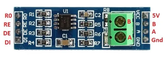
MAX485 Pinout
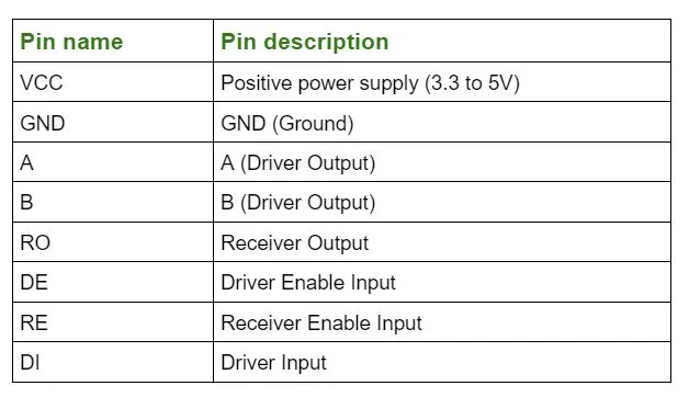
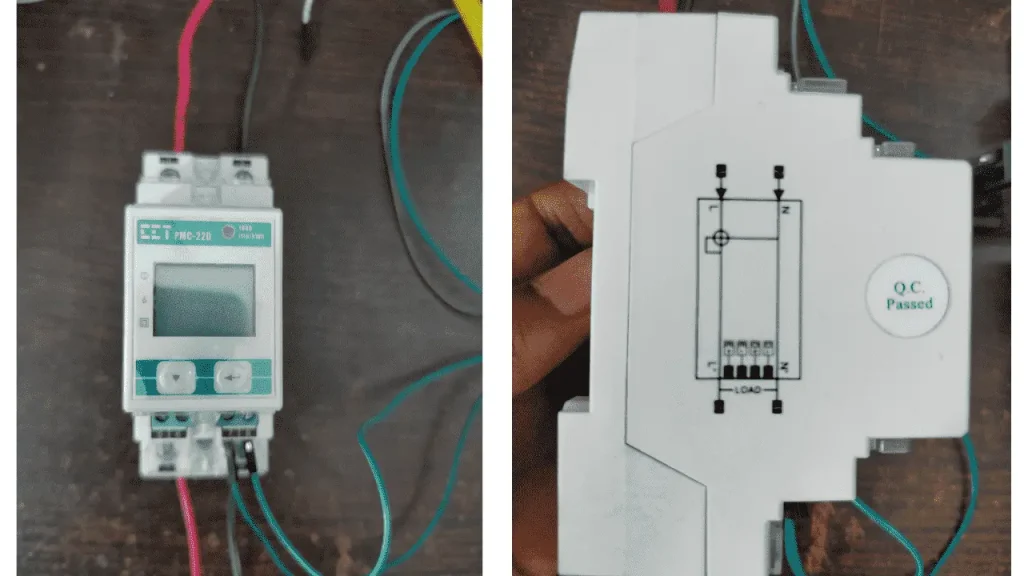
PMC-220 Energy Meter
The PMC-220 is a single phase AC energy meter device designed for accurate measurement and monitoring of electrical energy consumption, featuring RS485 communication capabilities. This energy meter offers a wide range of features, including high precision measurement capabilities and real-time data logging by using RS485 communication protocol.
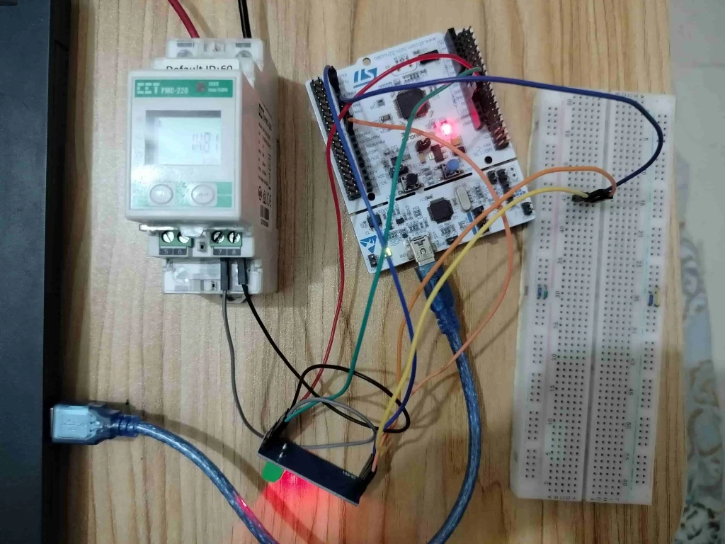
How to interface STM32 with RS485 (Modbus) sensors: The Project
In this section of the tutorial, we will first draw the circuit diagram of the rs485 communication between STM32 (as master) and PMC-220 energy meter (as a slave sensor). You can use any rs485 based sensors. After that, we will code an example project which is to collect the voltage (in Volt) data from PMC-220 energy meter using MAX485 module to STM32. We will be using STM32 NUCLEO-F446RE development board for this project, we can use any STM32 development board available in the market. At last we will show the collected data using Live Expression feature of STM32CubeIDE debug window.
Component List
| Component Name | Quantity | Purchase Link |
|---|---|---|
| STM32 Development Board | 1 | Amazon | AliExpress |
| RS485 based Energy Meter | 1 | Amazon | AliExpress |
| MAX485 Module | 1 | Amazon | AliExpress |
| Breadboard | 1 | Amazon | AliExpress |
| Jumper Wire Set | 1 | Amazon | AliExpress |
Affiliate Disclosure: When you click on links to make a purchase, this can result in this website earning a commission.
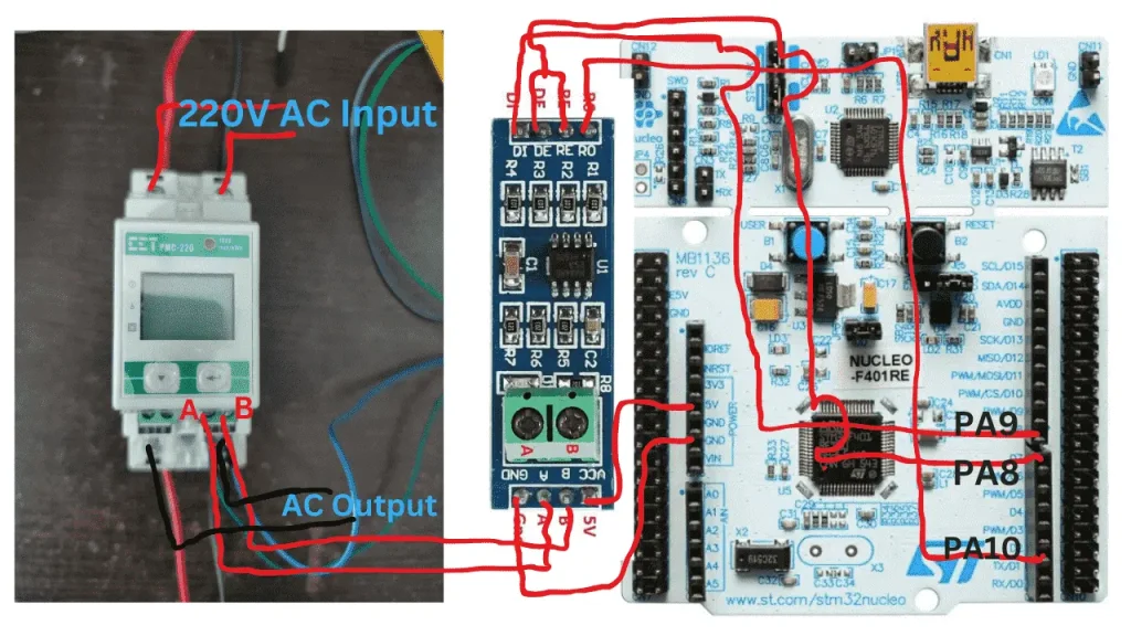
Circuit Connection between STM32, MAX485 and PMC-220
| STM32 Nucleo Board Pin | MAX485 Pin | PMC-220 Pin |
|---|---|---|
| 5V | Vcc | |
| Gnd | Ground | |
| Port A Pin 8 (PA8) | DE, RE | |
| Port A Pin 9 (PA9) | DI | |
| Port A Pin 9 (PA9) | RO | |
| A | 7 | |
| B | 8 |
Circuit Diagram
Preparing STM32CubeIDE for the project
For project creation in Stm32CubeIDE, please visit your previous tutorial. The link is given below:
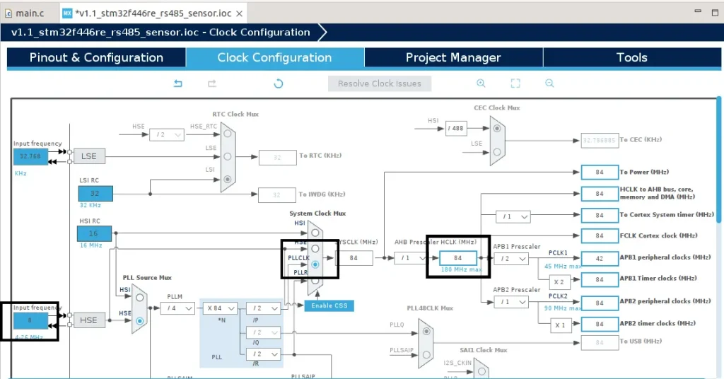
After creating the STM32CubeIDE project, from the CubeMX perspective open the Clock Configuration setting of the STM32Cube IDE and select the clock source (HSI or HSE). We select the External clock source (HSE) of 8 MHz and generate an 84MHz clock using PLL of STM32 microcontroller for this example project.
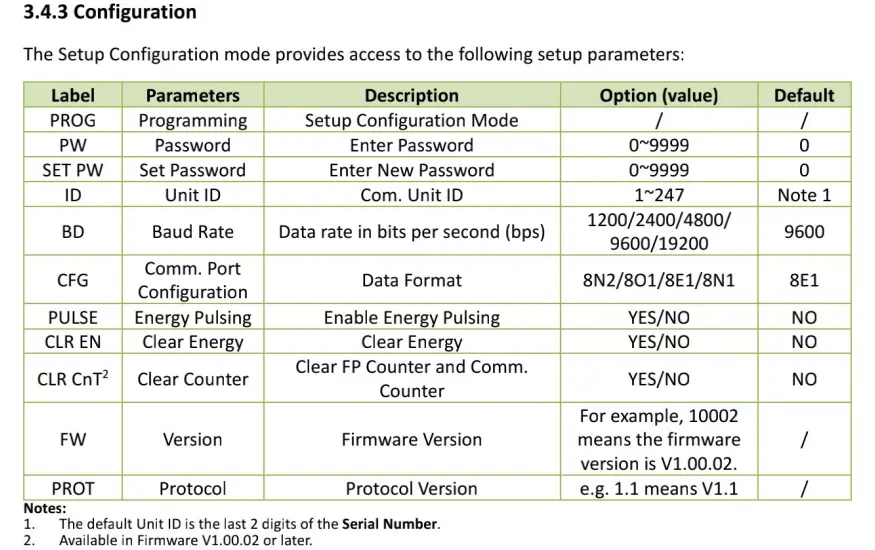
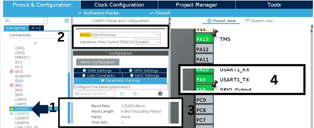
After clock configuration go to Pinout & Configuration tab and select USART1 from Connectivity options. We will be using STM32 USART1 peripheral to communicate with MAX485 module. Configure the peripheral as Asynchronous mode. Alos, set the baud rate as 115200 Bits/s, Word Length set to 8-bit, stop Bits set to 1 and Parity as None. We set all these settings according to the Energy Meter datasheet.
We also select Port A pin 9 (PA9 ) as USART1 TX and Port A pin 10 (PA10) as USART1 RX. Also, PA8 as output which is connected to DE and RE pin of MAX485 module. RE and RE pin of max485 control the data direction (Receiver or Transmitter) of RS485 protocol.
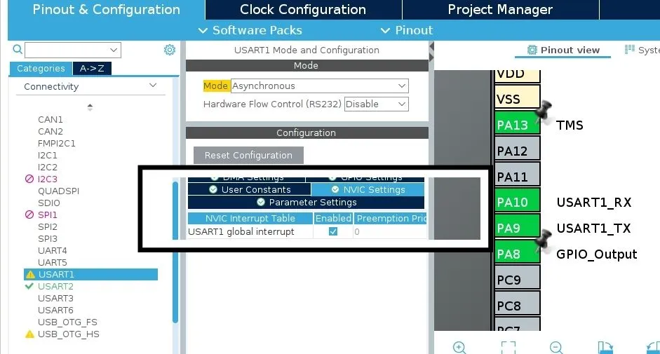
We also enable USART1 Global Interrupt for receiving data instantly from the energy meter through the MAX485 module.
Code Explanation
uint8_t uart1_tx_data[8];
uint8_t uart1_rx_data[15];
uint16_t recv_data[2];

void modbus_tx_data(){
	uart1_tx_data[0] = 0x41; // slave address
	uart1_tx_data[1] = 0x03; // Function code for Read Input Registers (0x03)

	// this 2 byte indicate the first 16-bit register.
	// where we want to start reading
	//The Register address will be 00000000 00000000 (40001)
	uart1_tx_data[2] = 0x00;
	uart1_tx_data[3] = 0x00;

	// this 2 byte indicate how many 16-bit register we want to read.
	// we will read 2, 16-bit data register from_
	// 00000000 00000000 to 00000000 00000001 (from 40001 to 40002 according to salve datasheet)
	uart1_tx_data[4] = 0x00;
	uart1_tx_data[5] = 0x02;

	// CRC Check function
	uint16_t crc = crc16(uart1_tx_data, 6);
	uart1_tx_data[6] = crc & 0xFF; //CRC LOW
	uart1_tx_data[7] = (crc >> 8) & 0xFF; //CRC HIGH

	// set DE,RE pin LOW to set max485 as transmitter mode
	HAL_GPIO_WritePin(GPIOA, GPIO_PIN_8, SET);
	// sending the uart1_tx_data array
	HAL_UART_Transmit(&huart1, uart1_tx_data, 8, 1000);
	// set DE,RE pin HIGH to set max485 as receiver mode
	HAL_GPIO_WritePin(GPIOA, GPIO_PIN_8, RESET);

}
uart1_tx_data this 8-bit array is use to send data request to Modbus slave device in Modbus standard format.
uart1_rx_data is array is use to receive and store the data from Modbus slave.
We will use recv_data 16-bit array to combine the two 8-bit data into one 16-bit register because Modbus send the data in 16-bit format.
After that, we create a function called modbus_tx_data() to format and send the command according to the Modbus protocol.
crc16() function is used to calculate the CRC check. Download the project files from GitHub and add modbus_crc.h and modbus_crc.c file to the respective folder of the STM32CubeIDE project.

HAL_UARTEx_ReceiveToIdle_IT(&huart1, uart1_rx_data, 32);
This is a HAL api enable the receive interrupt.
void HAL_UARTEx_RxEventCallback(UART_HandleTypeDef *huart, uint16_t Size){
	recv_data[0] = uart1_rx_data[3]<<8 | uart1_rx_data[4];
	recv_data[1] = uart1_rx_data[5]<<8 | uart1_rx_data[6];
}
This HAL_UARTEx_RxEventCallback function triggered, when the interrupt gets called. Inside the function we write the code to combine the two 8-bit data into one 16-bit Modbus register coming from the energy meter.
while (1)
  {
    modbus_tx_data();
    HAL_Delay(1000);
  }
This the infinite while(1) loop, we just call the modbus_tx_data() function every one second and request for the data from slave in Modbus protocol format.
Full Code
/* Includes -*/
#include "main.h"
#include "stdint.h"
#include "modbus_crc.h"

/* Private variables */
UART_HandleTypeDef huart1;
UART_HandleTypeDef huart2;

/* Private function prototypes */
void SystemClock_Config(void);
static void MX_GPIO_Init(void);
static void MX_USART2_UART_Init(void);
static void MX_USART1_UART_Init(void);

uint8_t uart1_tx_data[8];
uint8_t uart1_rx_data[15];
uint16_t recv_data[2];

void modbus_tx_data(){
	uart1_tx_data[0] = 0x41; // slave address
	uart1_tx_data[1] = 0x03; // Function code for Read Input Registers (0x03)

	// this 2 byte indicate the first 16-bit register.
	// where we want to start reading
	//The Register address will be 00000000 00000000
	uart1_tx_data[2] = 0x00;
	uart1_tx_data[3] = 0x00;

	// this 2 byte indicate how many 16-bit register we want to read.
	// we will read 2, 16-bit data register from_
	// 00000000 00000000 to 00000000 00000001
	uart1_tx_data[4] = 0x00;
	uart1_tx_data[5] = 0x02;

	// CRC Check function
	uint16_t crc = crc16(uart1_tx_data, 6);
	uart1_tx_data[6] = crc & 0xFF; //CRC LOW
	uart1_tx_data[7] = (crc >> 8) & 0xFF; //CRC HIGH

	// set DE,RE pin LOW to set max485 as transmitter mode
	HAL_GPIO_WritePin(GPIOA, GPIO_PIN_8, SET);
	// sending the uart1_tx_data array
	HAL_UART_Transmit(&huart1, uart1_tx_data, 8, 1000);
	// set DE,RE pin HIGH to set max485 as receiver mode
	HAL_GPIO_WritePin(GPIOA, GPIO_PIN_8, RESET);

}

/**
  * @brief  The application entry point.
  * @retval int
  */
int main(void)
{
  /* Reset of all peripherals, Initializes the Flash interface and the Systick. */
  HAL_Init();

  /* Configure the system clock */
  SystemClock_Config();

  /* Initialize all configured peripherals */
  MX_GPIO_Init();
  MX_USART2_UART_Init();
  MX_USART1_UART_Init();

  // Enable the receive interrupt
  HAL_UARTEx_ReceiveToIdle_IT(&huart1, uart1_rx_data, 32);

  /* Infinite loop */
  /* USER CODE BEGIN WHILE */
  while (1)
  {
    modbus_tx_data();
    HAL_Delay(1000);
  }
  /* USER CODE END 3 */
}

// The following function is called when the interrupt gets triggered
void HAL_UARTEx_RxEventCallback(UART_HandleTypeDef *huart, uint16_t Size){
	recv_data[0] = uart1_rx_data[3]<<8 | uart1_rx_data[4];
	recv_data[1] = uart1_rx_data[5]<<8 | uart1_rx_data[6];
}
Please Note: Certain portions of the code, specifically those automatically generated by STM32CubeIDE, have been omitted.
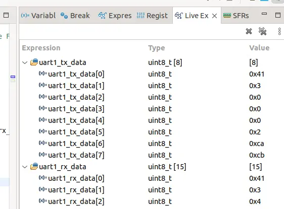
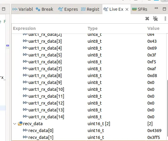
Output of the Code
Below are the images of the STM32 debug window showing the request sent by the master (in this case our STM32 Microcontroller) and the response received by the master from the slave (our Energy meter PMC-220). After receiving the 4-byte of data from the index of uart1_rx_data[3] to uart1_rx_data[6], we combine the received data to a 16-bit array called recv_data[2] because the Modbus holding register sends 16-bit data at a time. If you typecast the recv_data array to float you will find the voltage value which is mentioned in the Energy Meter datasheet.
PMC-220 energy meter RS485 (Modbus RTU) register reference