
In today’s rapidly evolving world, where energy efficiency is crucial for sustainable living, the Internet of Things (IoT) offers innovative solutions to monitor and manage energy consumption. In this article, we will explore an IoT-based energy monitoring system that utilizes the ESP32 microcontroller and CT sensor to track and analyze energy usage in real time. By implementing such a system, individuals and businesses can gain insights into their energy consumption patterns and make informed decisions to optimize their energy usage.
Our other ESP32-related tutorials are:
- How to Interface ESP32 with SIM7600 4G LTE Module using Arduino IDE
- Esp32 LoRa tutorial using Arduino IDE with example code
- How to install ESP32 Board in Arduino IDE
- How to interface ESP32 with RS485 (Modbus) sensors with example code
- ESP32 LoRaWAN Gateway tutorial with Sensor Node
Understanding IoT-based Energy Monitoring Systems
IoT-based energy monitoring systems leverage the power of interconnected devices to gather, analyze, and visualize energy consumption data. By integrating sensors, microcontrollers, and communication protocols, these systems enable users to track their energy usage in real-time and make data-driven decisions for energy optimization. Such systems provide valuable insights into energy consumption patterns, identify wastage, and help individuals and organizations adopt sustainable practices.
SCT-013 Current Sensor
The SCT013 CT sensor is a popular Current Transformer (CT) sensor used in energy monitoring systems. It is designed to measure alternating current (AC) flowing through a conductor without the need for direct electrical contact which means it’s a Non-invasive sensor. It is a clamp meter sensor which is clamped phase or neutral wire of a power line but clamping on a neutral wire provides us more appropriate result. We can measure 0 to 100A current using SCT-013. Depending on output there are two types of SCT-013 available in the market. One provides voltage (0 to 1V) output and the other provides current (0 to 50mA) output.

The secondary of a Current Transformer (CT) cannot keep open because open secondary makes infinity voltage (practically 1000V) that causes damage to your sensor permanently. So we need a resistor to reduce this high voltage and it’s called a burden resistor. The voltage output type SCT-013 has a built-in burden resistor but the current output type has no built-in burden resistor. For Arduino the value of the burden resistor is 33Ω and for ESP32 it is 22 Ω.
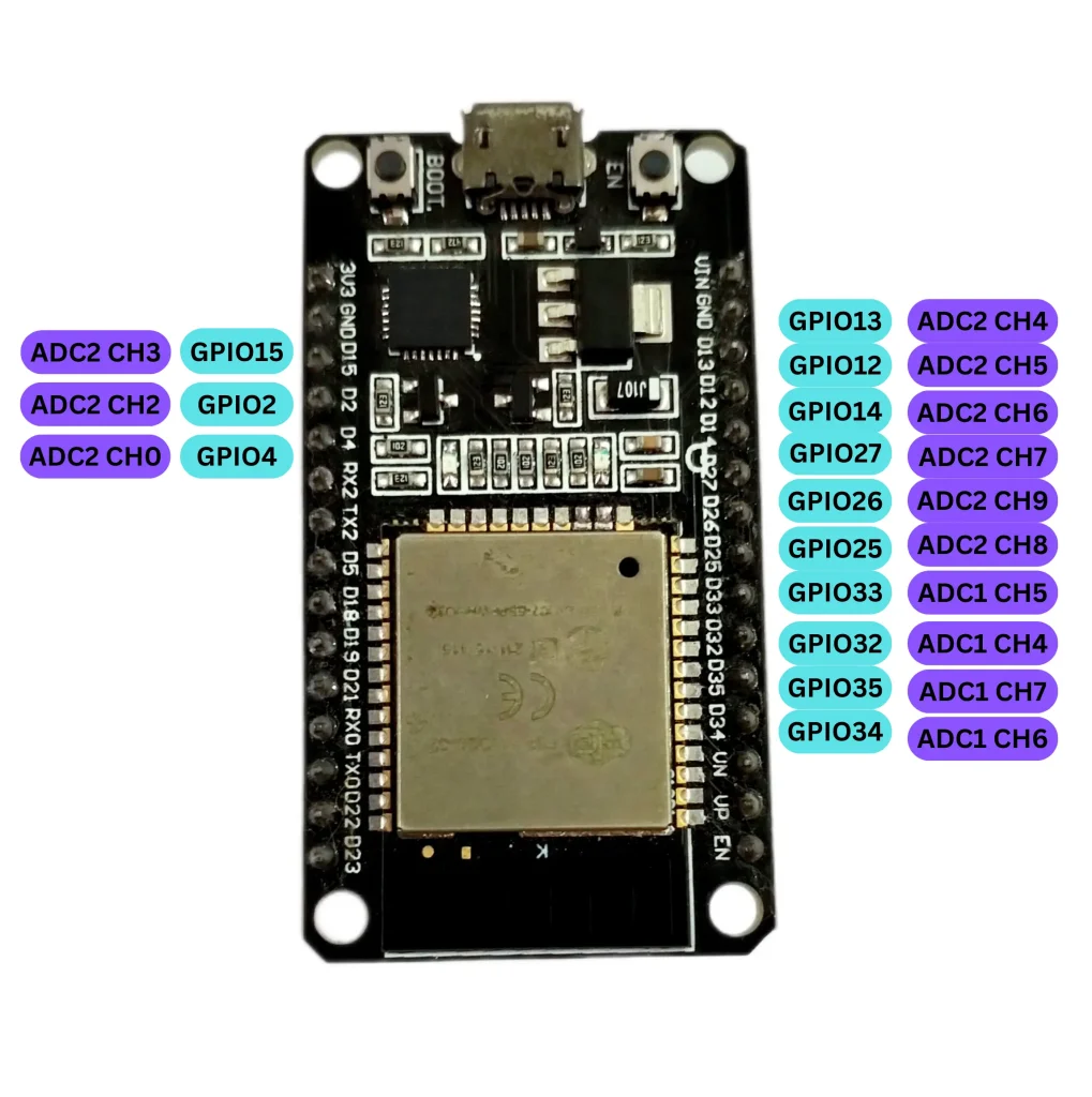
Understanding of ESP32 Analog to Digital Converter (ADC)
SCT-013 provides us 0-1V or 0-50mA output which means for 0A SCT-013 gives 0V, for 50A it gives 0.5V, for 100A it provides 1V. These output values are not digital (i.e. 0V or 3.3V). these are analog values. So, we need to convert these values to digital. At this time ESP32 will help us. ESP32 has a 12-bit ADC with 18 measurement channels.
To read the analog value, you need to trigger the ADC conversion and wait for it to complete. The ADC converts the analog voltage on the input pin into a digital value, which can be read from the ADC register. The value will be between 0 and 4095 (2^12=4096, one for 0 so it’s 4095), representing the voltage level in the range of 0V to the reference voltage (usually 3.3V). Once you have the digital value from the ADC, you can convert it back to the corresponding voltage using the formula:
Voltage = (Digital value / 4095) * Reference voltage
The resulting Voltage will represent the corresponding voltage value in the range of 0 to 3.3V. For example, if digital Value is 2048, the calculation would be:
Voltage = (2048 / 4095) * 3.3 = 1.65V
Therefore, a digital value of 2048 would correspond to a voltage of 1.65V.
Keep in mind that this calculation assumes a 3.3V reference voltage for the ADC. If your ESP32 is configured with a different reference voltage, you would need to adjust the formula accordingly.
Sending Data to an IoT Cloud
To send sensor data we will use Google Firebase in this project. Google Firebase is a comprehensive platform-as-a-service (PaaS) solution offered by Google that provides a range of tools and services for developing and managing web and mobile applications. While Firebase is commonly associated with mobile app development, its features and capabilities have proven to be valuable for Internet of Things (IoT) applications as well. Some core features of Google Firebase:
- Real-time Database: Firebase’s Real-time Database is a NoSQL cloud-hosted database that enables real-time synchronization of data across connected devices. This feature is highly relevant to IoT applications, as it allows devices to communicate and share data seamlessly. IoT devices can push sensor readings, status updates, and other relevant information to the Firebase Real-time Database, ensuring that all connected devices receive the latest data instantly. This real-time synchronization is critical for IoT applications that require quick decision-making and timely responses.
- Authentication and Security: IoT devices often handle sensitive data and require secure communication channels. Firebase provides robust authentication and security features, including user authentication, identity management, and access control. This allows developers to implement secure user authentication mechanisms, ensuring that only authorized individuals or devices can access and interact with IoT systems. Firebase’s security features help protect IoT applications from unauthorized access and potential data breaches.
- Analytics and Monitoring: Firebase’s analytics and monitoring capabilities are valuable for gaining insights into IoT application usage, device performance, and user behavior. By integrating Firebase Analytics into an IoT application, developers can track and analyze metrics such as device connections, user engagement, data usage, and more. This data-driven approach helps optimize IoT applications, identify bottlenecks, and make informed decisions to enhance the overall user experience.
Creating a Google Firebase Account
Step 01: Go to firebase.com and sign up with your Google (Gmail) account.
Step 02: Click get started and create a project.
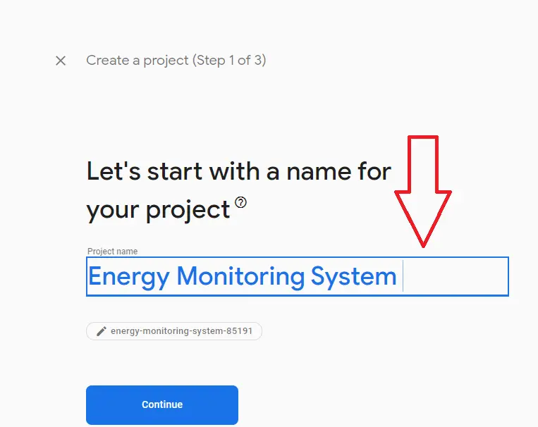
Step 03: Write your project name and continue.
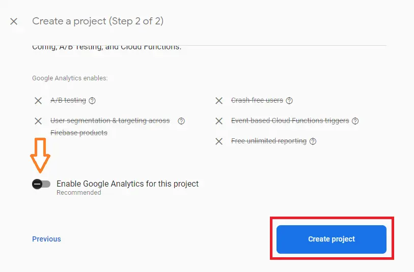
Step 04: Disable Google Analytics and click create project.
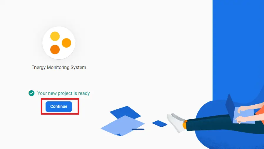
Step 05: You can see your project name and click continue.
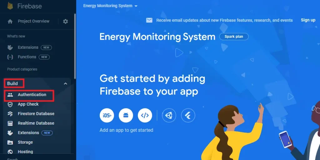
Step 06: Go to build>> Authentication
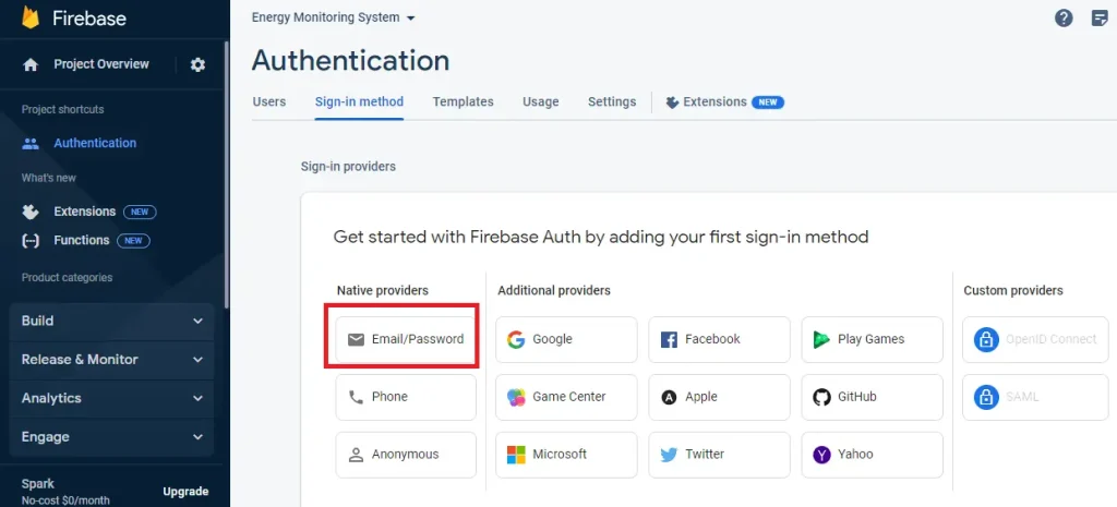
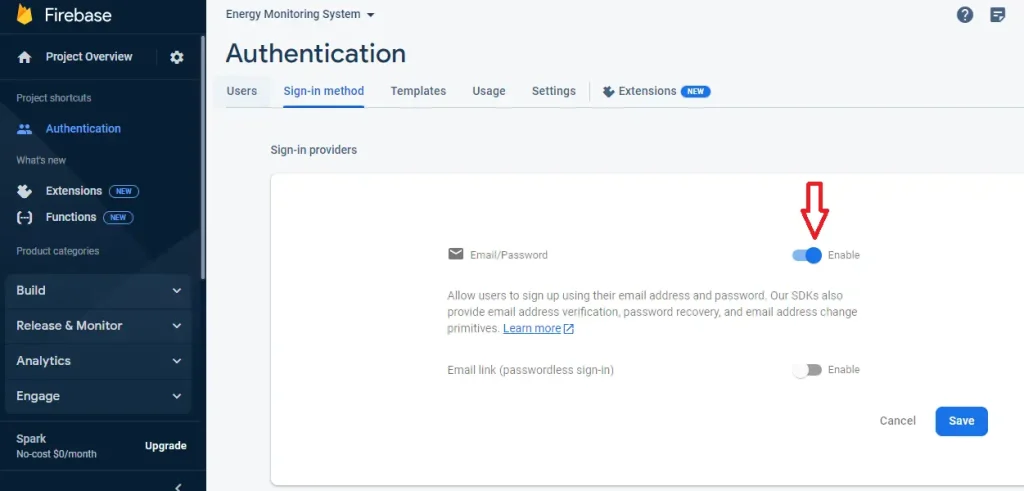
Step 07: Select the signup method. I selected Email/password.
Step 08: Enable Email/password and save.
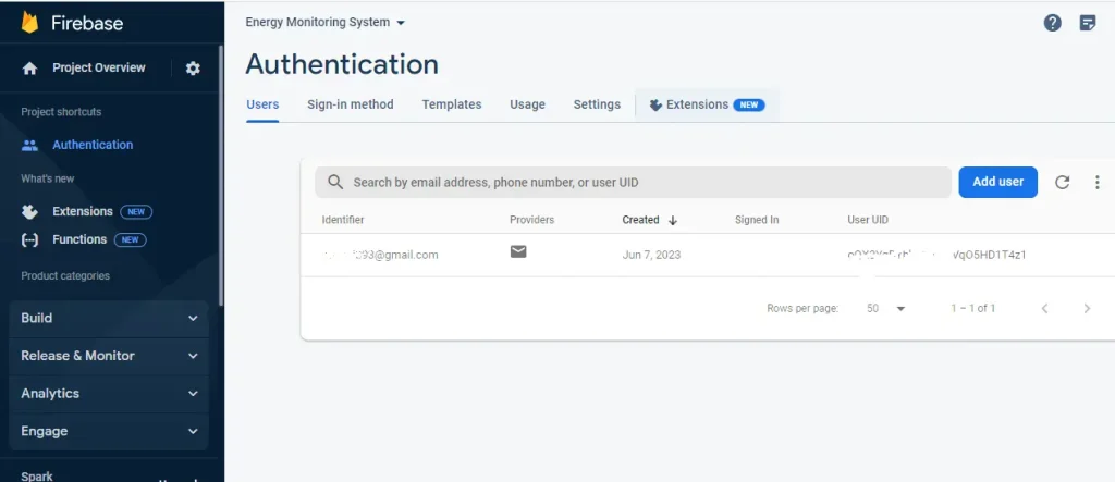
Step 09: Click Add user
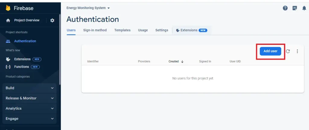
Step 10: Give an email and password.
Step 11: Go to Realtime Database
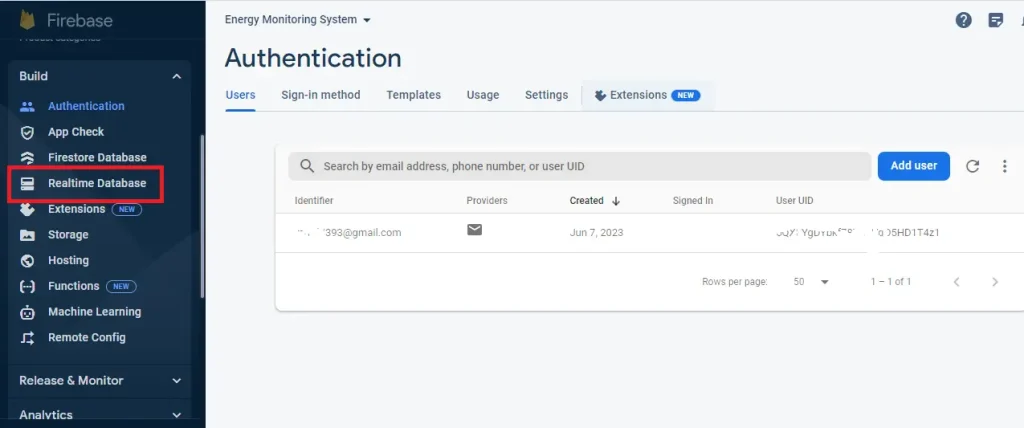
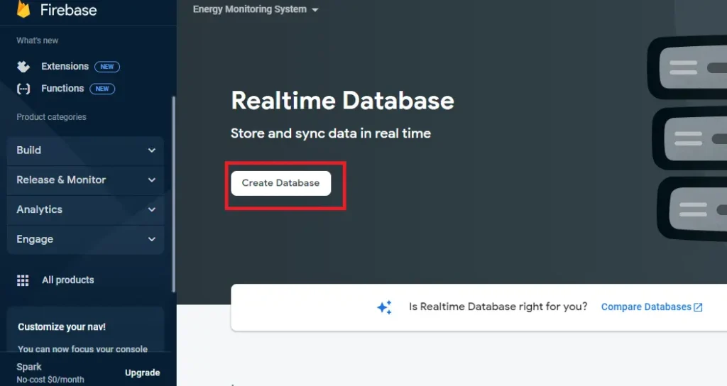
Step 12: Click Create Database
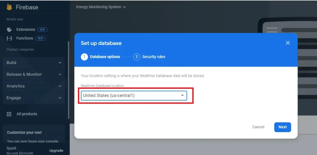
Step 13: Select your nearest server
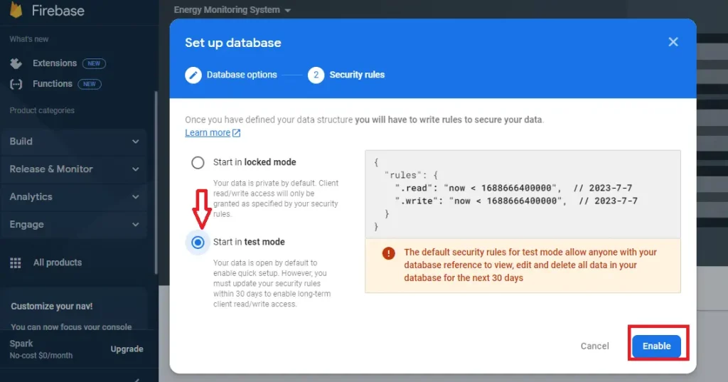
Step 14: Select start in test mode and click enable
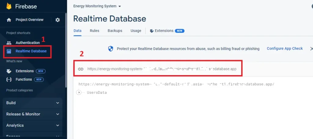
Step 15: go to real time database option and copy the database URL and paste it to DATABASE_URL of your esp32 code.
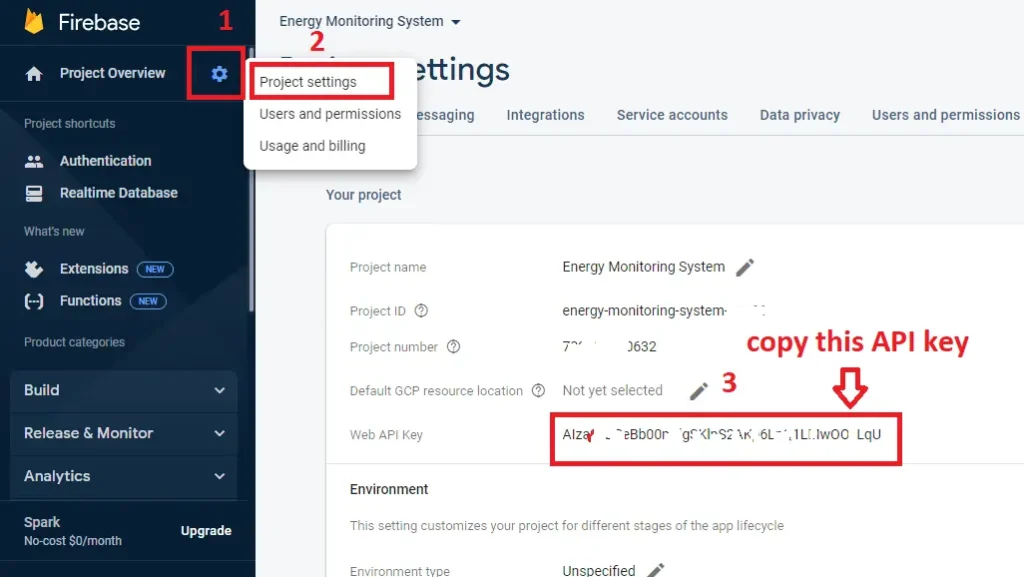
Step 16: For the Firebase API key click the gear icon and go to project settings. Copy the API key and past into your ESP32 code at the Firebase API line.
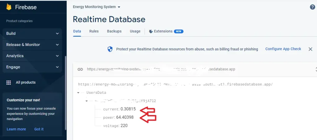
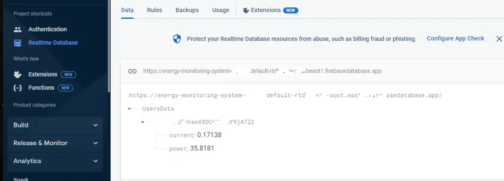
Step 17: And you are done. After uploading ESP32 code you can see the value on this page.
Step 18: For the second time to find your project click Go to the console and you will see your project name.

Component list
| Component Name | Quantity | Purchase Links |
|---|---|---|
| ESP32 Development Board | 1 | Amazon | AliExpress |
| SCT-013 Current Sensor | 1 | Amazon | AliExpress |
| One 10K Ohm, One 22 Ohm Resistor | 3 | Amazon | AliExpress |
| 10 uF Capacitor | 1 | Amazon | AliExpress |
| Jumper Wire | 1 | Amazon | AliExpress |
| Breadboard | 1 | Amazon | AliExpress |
Affiliate Disclosure: When you click on links to make a purchase, this can result in this website earning a commission. Affiliate programs and affiliations include, but are not limited to Amazon.com
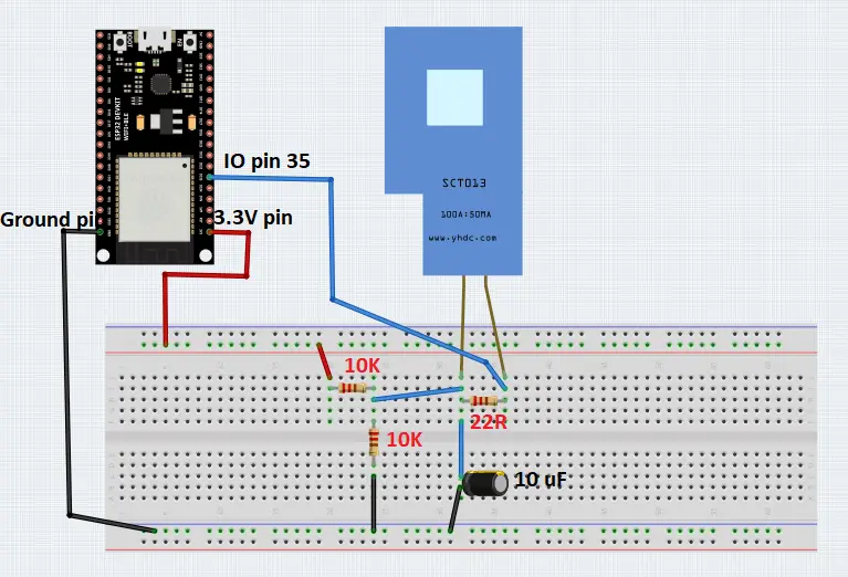
Circuit Diagram
Install libraries in Arduino IDE
Before moving into the code, we need to install some libraries those will save your time.
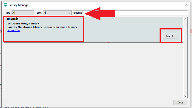
Open your Arduino IDE. To install Eomon Library go to Tools>>Manage Libraries and search “EmonLib” and install.
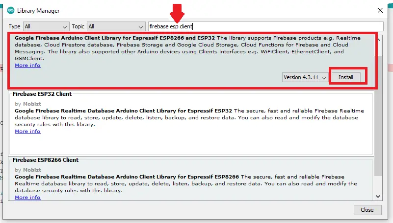
To install Firebase Library go to Tools>>Manage Libraries and search “firebase esp client” and install.
Code Description
Start with including some libraries such as wifi, Firebase, and EmonLib.
#include <Firebase_ESP_Client.h>
#include <Wire.h>
#include "EmonLib.h"
Define GPIO pin 35 as ADC input. You can choose any other ADC pin for your project. Define ADC_BITS as 12 because my ADC resolution is 12 bits.
#define ADC_INPUT 35
#define ADC_BITS    12
Create an instance as emon. Define wifi_ssid, and wifi_password where you will write your wifi name and password. In the firebase API section past your project API that is shown in the project settings. You added an email and password to your Firebase project in the Authentication section. Insert this email and its password. At last past your project URL. See “Creating Firebase Account and Project” section for more details.
EnergyMonitor emon;
#define WIFI_SSID "write_your_wifi_ssid"
#define WIFI_PASSWORD "write_your_wifi_password"
#define API_KEY "past_Your_Firebase_API"
#define USER_EMAIL "Write_your_email"
#define USER_PASSWORD "Write_your_Authentication_email_password"
#define DATABASE_URL "Past_your_real_time_database_URL"
In this project, our main goal is to understand how to use a CT sensor and sending data to firebase. Hence to measure power we assume that the value of voltage and power factor are constant. So take two variables voltage and power factor(pf). In my country, the voltage is approximately 220V and the power factor is about 0.95. you can change these if you want.
float voltage=220.00;
float pf=0.95;
Define some Firebase objects to send data to the Firebase database.
FirebaseData fbdo;
FirebaseAuth auth;
FirebaseConfig config;
Assign some variables for Firebase database path.
String databasePath;
String voltagePath;
String currentPath;
String powerPath;
Initialize wifi. When the wifi SSID and password will be matched then an IP address will print on the serial monitor. If SSID and password doesn’t match then and line …… will show on the Arduino serial monitor.
void initWiFi() {
  WiFi.begin(WIFI_SSID, WIFI_PASSWORD);
  Serial.print("Connecting to WiFi ..");
  while (WiFi.status() != WL_CONNECTED) {
    Serial.print('.');
    delay(1000);
  }
  Serial.println(WiFi.localIP());
  Serial.println();
}
Create a function named sendFloat that will send the current, power and voltage value to the Firebase server. There are two arguments one is path and another one is value. For example, if we want to send a current value then we will call this function like this sendFloat(currentPath, current). When all the data will be passed a message “PASSED” will be shown on Arduino serial monitor and if fail to send data a “FAILED” message will show on the serial monitor.
void sendFloat(String path, float value){
  if (Firebase.RTDB.setFloat(&fbdo, path.c_str(), value)){
    Serial.print("Writing value: ");
    Serial.print (value);
    Serial.print(" on the following path: ");
    Serial.println(path);
    Serial.println("PASSED");
    Serial.println("PATH: " + fbdo.dataPath());
    Serial.println("TYPE: " + fbdo.dataType());
  }
  else {
    Serial.println("FAILED");
    Serial.println("REASON: " + fbdo.errorReason());
  }
}
Although ESP32 has maximum 12 bit resolution ADC you can change it by analogReadResolution() function. In this project we select 12 bit resolution. In setup function emon.current() function take two arguments the first one is ADC pin number and the second one is calibration. You may need to change calibration value for finding right reading. Rest of the lines are using to Initialize API, User email and password, database URL.
Serial.begin(115200);
analogReadResolution(ADC_BITS);
emon.current(35, 26);
initWiFi();
config.api_key = API_KEY;
auth.user.email = USER_EMAIL;
auth.user.password = USER_PASSWORD;
config.database_url = DATABASE_URL;
In the loop function, ESP32 reads the current value with the help of emon.Irms and send it to the Firebase server. Every 10 seconds the value will be updated and the updated value will send to the Firebase database. The values of current, power will be shown on Arduino serial monitor also.
if (Firebase.ready() && (millis() - sendDataPrevMillis > timerDelay || sendDataPrevMillis == 0)){
    sendDataPrevMillis = millis();
    emon.calcVI(20,2000);
    current = emon.Irms;
    power = voltage*current*pf;
    sendFloat(currentPath, current);
    sendFloat(powerPath, power);
  }

      Serial.print("Cureent: ");
      Serial.print(current);
      Serial.println(" Amps");
      Serial.print("Power: ");
      Serial.print(power);
      Serial.println(" Watts");
      delay(100);
}
Project Output
You can see your data from anywhere in the world in the real-time database section of Firebase.
Full code
Arduino IDE .ino file
#include <Arduino.h>
#if defined(ESP32)
#include <WiFi.h>
#elif defined(ESP8266)
#include <ESP8266WiFi.h>
#endif
#include <Firebase_ESP_Client.h>
#include <Wire.h>
#include "EmonLib.h"                   // Include Emon Library
#include <driver/adc.h>

#define ADC_INPUT 35                  // define IO pin 35 to read CT sensor value
#define ADC_BITS    12                // define ADC bit 12 for esp32 resulation

EnergyMonitor emon;                   // Create an instance
/******* You may need to change these lines *******/
// Insert your network credentials
#define WIFI_SSID "write_your_wifi_ssid"                           // Write your Wifi SSID or neme here
#define WIFI_PASSWORD "write_your_wifi_password"                     // Write your wifi password
// Insert Firebase project API Key
#define API_KEY "past_Your_Firebase_API" // Past your firebase api key here
// Insert Authorized Email and Corresponding Password
#define USER_EMAIL "Write_your_email"  // Write your firebase Authentication email and password
#define USER_PASSWORD "Write_your_Authentication_email_password" // Write your firebase Authentication password
// Insert RTDB URLefine the RTDB URL
#define DATABASE_URL "Past_your_real_time_database_URL"           // Past your real time batabase URL here

float voltage=220.00;                                 // change voltage
float pf=0.95;                                        // change power factor(pf)

WiFiClient client; //Initialize WiFi as client

// Provide the token generation process info.
#include "addons/TokenHelper.h"
// Provide the RTDB payload printing info and other helper functions.
#include "addons/RTDBHelper.h"

// Define Firebase objects
FirebaseData fbdo;
FirebaseAuth auth;
FirebaseConfig config;

// Variable to save USER UID
String uid;

// Variables to save database paths
String databasePath;
String voltagePath;
String currentPath;
String powerPath;

// Take some valiable
float current;
float power;

// Timer variables (send new readings every three minutes)
unsigned long sendDataPrevMillis = 0;
unsigned long timerDelay = 10000;

// Initialize WiFi
void initWiFi() {
  WiFi.begin(WIFI_SSID, WIFI_PASSWORD);
  Serial.print("Connecting to WiFi ..");
  while (WiFi.status() != WL_CONNECTED) {
    Serial.print('.');
    delay(1000);
  }
  Serial.println(WiFi.localIP());
  Serial.println();
}

// Write float values to the database
void sendFloat(String path, float value){
  if (Firebase.RTDB.setFloat(&fbdo, path.c_str(), value)){
    Serial.print("Writing value: ");
    Serial.print (value);
    Serial.print(" on the following path: ");
    Serial.println(path);
    Serial.println("PASSED");
    Serial.println("PATH: " + fbdo.dataPath());
    Serial.println("TYPE: " + fbdo.dataType());
  }
  else {
    Serial.println("FAILED");
    Serial.println("REASON: " + fbdo.errorReason());
  }
}

void setup(){
  Serial.begin(115200);
  analogReadResolution(ADC_BITS);    // 12 bit ADC

  emon.current(35, 26);             // Current: input pin, calibration // you can increase or decrease calibration argument to get right value from CT sensor
  initWiFi();

  // Assign the api key (required)
  config.api_key = API_KEY;

  // Assign the user sign in credentials
  auth.user.email = USER_EMAIL;
  auth.user.password = USER_PASSWORD;

  // Assign the RTDB URL (required)
  config.database_url = DATABASE_URL;

  Firebase.reconnectWiFi(true);
  fbdo.setResponseSize(4096);

  // Assign the callback function for the long running token generation task */
  config.token_status_callback = tokenStatusCallback; //see addons/TokenHelper.h

  // Assign the maximum retry of token generation
  config.max_token_generation_retry = 5;

  // Initialize the library with the Firebase authen and config
  Firebase.begin(&config, &auth);

  // Getting the user UID might take a few seconds
  Serial.println("Getting User UID");
  while ((auth.token.uid) == "") {
    Serial.print('.');
    delay(1000);
  }
  // Print user UID
  uid = auth.token.uid.c_str();
  Serial.print("User UID: ");
  Serial.println(uid);

  // Update database path
  databasePath = "/UsersData/" + uid;

  // Update database path for sensor readings
  voltagePath = databasePath + "/voltage"; // --> UsersData/<user_uid>/voltage
  currentPath = databasePath + "/current"; // --> UsersData/<user_uid>/current
  powerPath = databasePath + "/power"; // --> UsersData/<user_uid>/power
}

void loop(){

  // Send new readings to Firebase database
  if (Firebase.ready() && (millis() - sendDataPrevMillis > timerDelay || sendDataPrevMillis == 0)){
    sendDataPrevMillis = millis();
    emon.calcVI(20,2000);
    current = emon.Irms;                           // RMS value of current
    power = voltage*current*pf;                  // calculate power // take power factor as 0.95
    sendFloat(currentPath, current);                 // send current value to firebase
    sendFloat(powerPath, power);                     // send power value to firebase
  }

      Serial.print("Cureent: ");
      Serial.print(current);
      Serial.println(" Amps");
      Serial.print("Power: ");
      Serial.print(power);
      Serial.println(" Watts");
      delay(100);
}