
In this tutorial, we’ll walk you through the basics of Pulse Width Modulation (PWM) and how to create a stm32 project for generating PWM signals using Timer peripheral. We will also create a LED dimming project using PWM technique.
You may also like reading:
Our other STM32-related tutorials are:
- How to interface STM32 with RS485 (Modbus) sensors
- Getting Started with FreeRTOS in STM32
- Interfacing STM32 with I2C LCD : HAL example code included
- How to create a project in stm32CubeMX for Keil uvision Ide
- How to create stm32 project in stm32cubeide with example code
- STM32 ADC tutorial using DMA with HAL Code Example
- Stm32 Bluetooth module HC-05 interfacing with HAL code example
Introduction
Pulse Width Modulation (PWM) is a widely used technique in embedded systems to control the power delivered to electronic components, such as motors, LEDs, and servos. It’s a method of producing analog-like signals from digital microcontrollers. If you’re working with STM32 microcontrollers and want to dive into PWM, you’re in the right place.
What is PWM?
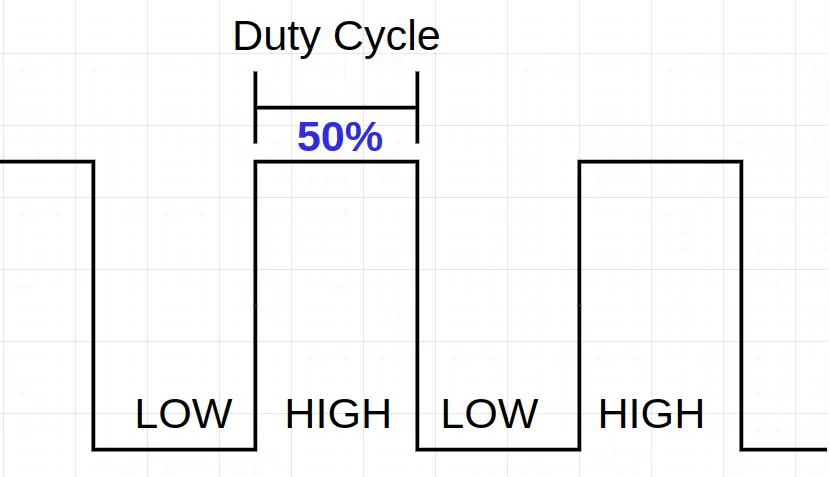
At its core, PWM involves rapidly toggling a digital signal between high and low levels with varying duty cycles. The duty cycle represents the portion of time the signal spends in the high state within a given period. By adjusting the duty cycle, you can effectively control the average voltage or current applied to a load, allowing you to control its behavior.
For example, if you want to generate a 2.5V signal from a digital source like a microcontroller which provides either HIGH(5V) or LOW (0V) signal only. We can generate a duty cycle of 50% by the help of PWM. This 50% duty cycle will produce an average voltage of 5×0.5=2.5V.
LED dimming project using STM32 PWM technique
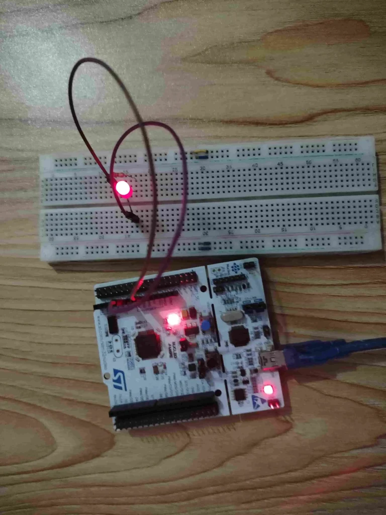
In this section of the tutorial, we will create a LED dimming project in STM32CubeIDE by using STM32 HAL (Hardware Abstraction Layer) api. We will control the brightness of the LED by generating PWM signal using the Timer 2 peripheral of STM32F446RE microcontroller.
Component List
| Component Name | Quantity | Purchase Link |
|---|---|---|
| STM32 Development Board | 1 | Amazon |
| 5mm LED | 1 | Amazon |
| 330 ohm resistor | 1 | Amazon |
| Breadboard | 1 | Amazon |
| Jumper Wire Set | 1 | Amazon |
For troubleshooting, some extremely useful test equipment
| Equipment Name | Purchase Link |
|---|---|
| Best Oscilloscope for Professionals | Amazon |
| Best Oscilloscope for Beginners and Students | Amazon |
| Logic Analyzer | Amazon |
| Best Budget Multimeter | Amazon |
| Adjustable Bench Power Supply | Amazon |
Affiliate Disclosure: When you click on links to make a purchase, this can result in this website earning a commission. Affiliate programs and affiliations include, but are not limited to Amazon.com
Circuit Diagram
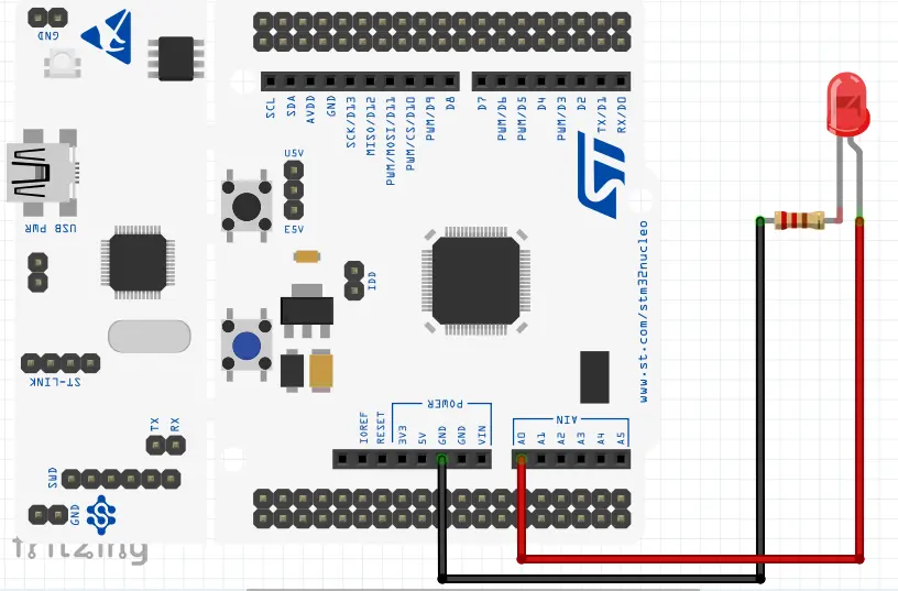
Pin Connections
| STM32 NUCLEO Board | LED Pin |
|---|---|
| GPIO A Pin 0 (PA0)/ A0 | Anode of LED |
| Ground | Cathode of LED with 330 ohm resistor in series |
Preparing STM32CubeIDE
For project creation in Stm32CubeIDE, please visit your previous tutorial. The link is given below:
After creating the STM32CubeIDE project, from the CubeMX perspective open Clock Configuration setting and select the clock source (HSI or HSE). We select the External clock source (HSE) of 8 MHz and generate an 80MHz clock using PLL of STM32 microcontroller for this example project.
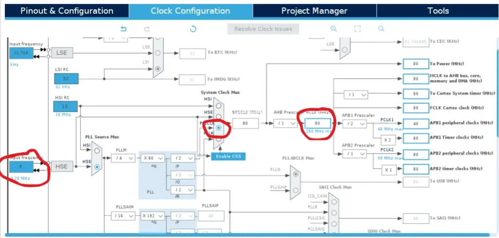
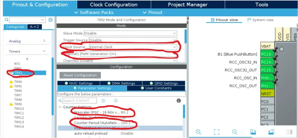
After that go to Pinout & Configuration tab and select your Timer. We will use Timer 2 (TIM2) for this project. Then go to Mode section of Timer 2 and select Clock Source as Internal Clock and Channel as PWM generation CH1.
After that click on Parameters Settings and change the Prescaler and Period value to your requirements. We set the prescaler as 80 MHz to configure the Timer clock of 1MHz. After that we set the ARR (Counter Period) value as 100.
For both the parameters, we add -1 because the Prescalar Register and the ARR Register of STM32 already add 1 in their register setup.
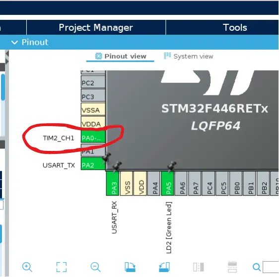
Now, select the GPIO pin for the TIM2 PWM channel 1 for generating the signal. We selected the PA0 pin of STM32F446RE microcontroller for the LED dimming project.
Code Explanation
HAL_TIM_PWM_Start(&htim2, TIM_CHANNEL_1);
This is a HAL api for STM32 PWM initialization. This api except two arguments and they are Timer peripheral number and Timer channel number. In our case the timer peripheral in Timer 2 (TIM2) and Channel 1.
/* Infinite loop */
  while (1)
  {
    /* PWM range from 0% to 100% */
	  for(int i=0; i<=100; i++){
		  TIM2->CCR1 = i;
		  HAL_Delay(5);
	  }

	  /* PWM range from 100% to 0% */
	  for(int i=100; i>=0; i--){
		  TIM2->CCR1 = i;
		  HAL_Delay(15);
	  }
  }
}
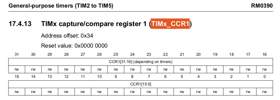
In the infinite while loop, we first increase the LED brightness form low to high (0% to 100%) by increasing the CCR1 (Timer Channel 1) register value. Then we decrease the LED brightness from high to low (100% to 0%) by decreasing the CCR1 value. To learn about the Capture Compare Register (CCR), please read your STM32 microcontroller datasheet Timer section.
For example, we set our timer clock frequency to 1MHz and the counter register (ARR) value is 100 from the STM32CubeIDE configuration setting which showed earlier. If we need 40% duty cycle the formula is:
PWM frequency = 1MHz / 100 = 10KHz
So, for 40% duty cycle CCR value is = (40/ARR)*100 = (40/100)*100 = 40
Or, if we need 30% duty cycle then the CCR value is: (30/ARR)*100 = (30/100)*100 = 30
Full Code
STM32CubeIDE main.c file
/* Includes */
#include "main.h"

/* Private variables */
TIM_HandleTypeDef htim2;

UART_HandleTypeDef huart2;

/* Private function prototypes */
void SystemClock_Config(void);
static void MX_GPIO_Init(void);
static void MX_USART2_UART_Init(void);
static void MX_TIM2_Init(void);

/**
  * @brief  The application entry point.
  * @retval int
  */
int main(void)
{
  /* MCU Configuration-*/

  /* Reset of all peripherals, Initializes the Flash interface and the Systick. */
  HAL_Init();

  /* Configure the system clock */
  SystemClock_Config();

  /* Initialize all configured peripherals */
  MX_GPIO_Init();
  MX_USART2_UART_Init();
  MX_TIM2_Init();
  HAL_TIM_PWM_Start(&htim2, TIM_CHANNEL_1);

  /* Infinite loop */
  while (1)
  {
    /* PWM range from 0% to 100% */
	  for(int i=0; i<=100; i++){
		  TIM2->CCR1 = i;
		  HAL_Delay(5);
	  }

	  /* PWM range from 100% to 0% */
	  for(int i=100; i>=0; i--){
		  TIM2->CCR1 = i;
		  HAL_Delay(15);
	  }
  }
}
Please Note: Certain portions of the code, specifically those automatically generated by STM32CubeIDE, have been omitted.