
Timers are crucial in microcontroller-based systems, providing precise timing and control over various operations. In the case of STM32 microcontrollers, the built-in timers offer a wide range of functionalities and configurations. This tutorial will guide you through the basics of STM32 timers, their setup, and operation modes. We will also create a LED blinking project using STM32 Timer for demonstration purposes.
You may also like reading:
Our other STM32-related tutorials are:
- Getting Started with FreeRTOS in STM32
- Interfacing STM32 with I2C LCD : HAL example code included
- How to create a project in stm32CubeMX for Keil uvision Ide
- How to create stm32 project in stm32cubeide with example code
- STM32 ADC tutorial using DMA with HAL Code Example
- Stm32 Bluetooth module HC-05 interfacing with HAL code example
Understanding Timer Basics
What is Timer?
A timer is a hardware module used in electronic devices and microcontrollers. It counts events or clock cycles and triggers actions based on predetermined conditions. Timers are essential for precise timing and control in various applications. We can generate accurate delays, measure event durations, and control periodic actions by using timers.
How does Timer work in microcontrollers?
A timer utilizes a clock source and counter to measure and track time delay. The clock source provides a precise timing reference. While the counter job is to increment by one for each clock cycle. There are many control registers for times in the microcontroller for customization of the timer’s settings like timer prescaler and period configurations. Actions are triggered when the counter matches predefined values or conditions. Timers can generate output signals, interrupt, or initiate operations. Interrupts allow for timely responses to timing events or time-critical tasks.
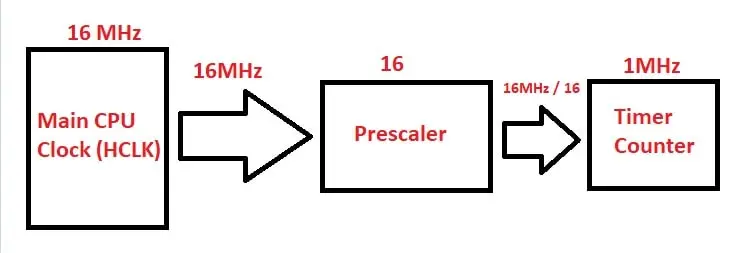
Timer Prescaler
A timer prescaler is a configurable division factor applied to the input clock signal. It adjusts the effective clock frequency before reaching the timer’s counter. The Prescaler value determines how many clock cycles are required for the counter to increment by one. It affects the timer’s resolution and range.
A higher prescaler value decreases the effective frequency and provides a coarser resolution. A lower prescaler value increases the effective frequency and offers a finer resolution. The prescaler allows for customization of timing accuracy and range in timer operations.
Timer Period Calculation
The timer period refers to the duration of one complete cycle of the timer. It represents the time it takes for the timer’s counter to reach its maximum value and reset back to zero. The maximum value is determined by the number of bits in the counter register. The timer period is determined by the clock frequency and the number of clock cycles required for one complete cycle. Number of clock cycles depends on the timer’s maximum value. For example, if you have a 16-bit timer, the maximum value is 65535 (2^16 – 1).
Timer period can be calculated using the formula: Period = (Number of Clock Cycles) / (Clock Frequency).
For example, let’s say you have a 16-bit timer with a maximum value of 65535 and a clock frequency of 10 MHz. The calculation would be:
Period = 65535 / 10,000,000 = 0.0065535s = 6.5535 ms
The timer period 6.5535 means the duration of one complete cycle of the timer. The timer period can be adjusted by changing the clock frequency or modifying the prescaler value. Understanding the timer period is crucial for tasks that require precise timing, such as generating delays or measuring time intervals.
Timers in STM32 Microcontroller
Types of STM32 Timers
STM32 microcontrollers offer different types of timers, each with its own set of features and capabilities. Here are the common types of timers found in STM32 microcontrollers:
General-Purpose Timers (TIM2-TIM5):
- These timers are versatile and commonly used for various timing and control tasks.
- They have advanced features like input capture, output compare, and PWM generation modes.
- General-purpose timers provide a wide range of functionality and flexibility.
Advanced-Control Timers (TIM1 and TIM8):
- These timers are designed for advanced control applications, such as motor control and power conversion.
- They offer more advanced features and precise control capabilities compared to general-purpose timers.
- Advanced-control timers provide additional features like complementary PWM outputs, advanced synchronization, and enhanced trigger options.
Basic Timers (TIM6 and TIM7):
- These timers are simpler in functionality compared to general-purpose and advanced-control timers.
- Basic timers are primarily used for basic timing tasks, such as generating interrupts at specific intervals.
- They are lightweight timers that offer an effective solution for basic timing requirements.
Each type of timer in STM32 microcontrollers has its own advantages and use cases. General-purpose timers provide the most versatility, while advanced-control timers are tailored for more complex control applications. Basic timers offer a simplified and cost-effective solution for basic timing needs. The specific type of timer to use depends on the requirements of the application and the desired functionality.
STM32 Timer Modes
Here are some of the common STM32 Time Modes
Time Base Generator:
- This mode allows the timer to generate a time base signal, which serves as a fundamental reference for other timer functionalities and operations.
- The Time Base Generation mode configures the timer to generate a periodic or non-periodic time base signal.
- This is used to generate the delay, specific operation done in each specific time interval (periodic operations) and etc.
Input Capture Mode:
- In this mode, the timer captures the value of an external signal’s rising or falling edge.
- It is useful for measuring the duration or frequency of external events.
- The captured values can be used for precise event timing, frequency analysis, or input signal measurements.
Output Compare Mode:
- Output compare mode compares the timer’s counter value with a predefined value.
- When a match occurs, it can trigger actions such as generating an output signal or interrupt.
- This mode is commonly used for tasks like generating precise PWM signals, triggering events at specific intervals, or implementing time-based control.
PWM Generation Mode:
- PWM generation mode allows the timer to generate Pulse Width Modulation (PWM) signals.
- PWM signals are widely used for controlling motor speed, LED brightness, and other applications that require varying power levels.
- This mode enables precise control over the duty cycle (ON time) and frequency of the PWM signals.
One-Pulse Mode:
- One-pulse mode configures the timer to generate a single pulse of a specific duration.
- It is useful for generating one-time events, such as triggering a specific action or producing a pulse for a fixed period.
If you look at the datasheet of your microcontroller, you will often find a section talking about the various timers available. As we will use the STM32 NUCLEO-F446RE development board for this tutorial which has an STM32F446RE microcontroller chip, we will follow the STM32F446RE datasheet.
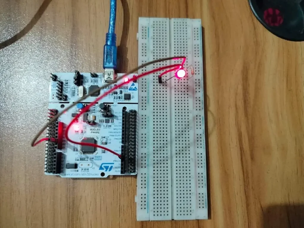
STM32 Timer Example Project
In this section of the tutorial, we will toggle a LED by using STM32 one of the basic timer which is Timer 6 (TIM6). We will configure the Timer 6 for 500 Milliseconds time delay. Also, we configure the timer for interrupt mode that means every 500 Milliseconds Timer 6 will generate an interrupt event and we will handle the event from our software and toggle the LED.
Component Lists
| Component Name | Quantity | Purchase Link |
|---|---|---|
| STM32 NUCLEO Development Board | 1 | Amazon |
| LED | 1 | Amazon |
| Resistor 220 ohm | 1 | Amazon |
| Breadboard | 1 | Amazon |
| Jumper wire pack | 1 | Amazon |
| USB Mini-B cable | 1 | Amazon |
For troubleshooting, some extremely useful test equipment
| Equipment Name | Purchase Link |
|---|---|
| Best Oscilloscope for Professionals | Amazon |
| Best Oscilloscope for Beginners and Students | Amazon |
| Logic Analyzer | Amazon |
| Best Budget Multimeter | Amazon |
| Adjustable Bench Power Supply | Amazon |
Affiliate Disclosure: When you click on links to make a purchase, this can result in this website earning a commission. Affiliate programs and affiliations include, but are not limited to Amazon.com
Circuit Diagram
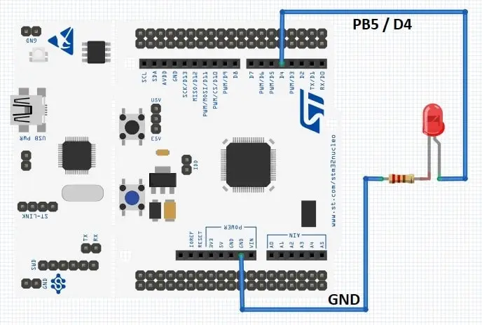
Pin Connections
| STM32 NUCLEO Board | LED Pin |
|---|---|
| GPIO B Pin 5 / D4 | Anode of LED |
| Ground | Cathode of LED |
Preparing STM32CubeIDE
For project creation in Stm32CubeIDE, please visit your previous tutorial. The link is given below:
After creating the STM32CubeIDE project, from the CubeMX perspective open Clock Configuration setting and select the clock source (HSI or HSE). We select the internal clock source (HSI) for this example project. STM32F446RE has a 16 MHz internal oscillator.
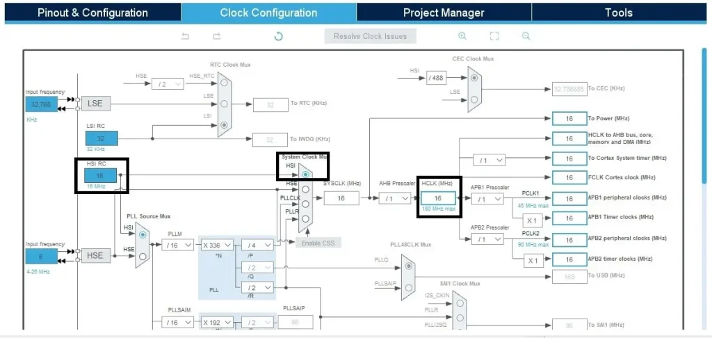
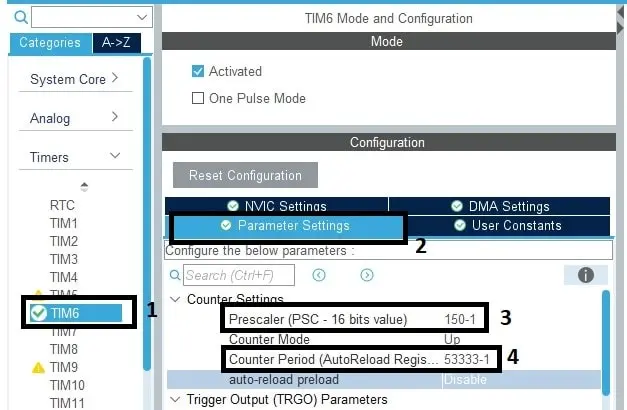
After that go to Pinout & Configuration tab and select your Timer. We will use Timer 6 (TIM6) for this project. Then click on Parameters Settings and change the Prescaler and Period value to your requirements.
We know, Timer Clock Frequency = MCU Clock Frequency / (1+Prescaler)
We will use a 500 milliseconds time delay for toggling a LED. So, we select Prescaler as 150-1 and Counter Period value as 53333-1. The time base calculation is given below:
Timer Clock Frequency = 16MHz / (1+149) = 160000000 Hz / 150 = 106666.66 Hz = 1/106666.66 = 0.000009374s
Count Period = time / clock after prescaler = 0.5 / 0.000009374 = 53333
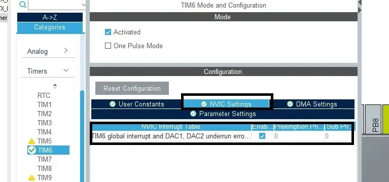
After the Timer configuration, click on NVIC Settings and Enable TIM6 global interrupt because we will toggle the LED using non-blocking (interrupt) mode.
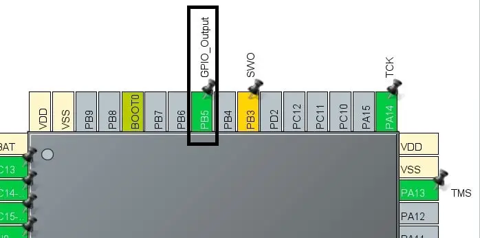
Then configure the GPIO B Pin 5 as output. We will connect our LED to this pin. In this NUCLEO board this PB5 pin is also connected to the D4 pin like Arduino.
Code Explanation
HAL_StatusTypeDef HAL_TIM_Base_Start_IT(TIM_HandleTypeDef *htim) API is used for timer initialization with interrupt mode. This API needs one parameter as input which is the Timer name.
HAL_TIM_Base_Start_IT(&htim6);
We configured Timer 6 with a time base of 500 ms. This means every 500 ms the timer will generate an event with a hardware interrupt. We need to handle the interrupt by using an API called HAL_TIM_PeriodElapsedCallback. You will find this API as __weak attribute in stm32f4xx_hal_tim.c file.
When the timer is triggered, we just toggle our LED which is connected with GPIO 5 of Port B. So, our LED will turn ON for 500ms and OFF for 500ms.
void HAL_TIM_PeriodElapsedCallback(TIM_HandleTypeDef *htim)
{
  HAL_GPIO_TogglePin(GPIOB, GPIO_PIN_5);
}
Full Code
main.c file of STM32CubeIDE
/* Includes */
#include "main.h"

/* Private variables */
 TIM_HandleTypeDef htim6;

UART_HandleTypeDef huart2;

/* Private function prototypes */
void SystemClock_Config(void);
static void MX_GPIO_Init(void);
static void MX_USART2_UART_Init(void);
static void MX_TIM6_Init(void);

/**
  * @brief  The application entry point.
  * @retval int
  */
int main(void)
{
  /* MCU Configuration*/

  /* Reset of all peripherals, Initializes the Flash interface and the Systick. */
  HAL_Init();

  /* Configure the system clock */
  SystemClock_Config();

  /* Initialize all configured peripherals */
  MX_GPIO_Init();
  MX_USART2_UART_Init();
  MX_TIM6_Init();
  /* USER CODE BEGIN 2 */
  HAL_TIM_Base_Start_IT(&htim6);
  /* USER CODE END 2 */

  /* Infinite loop */
  /* USER CODE BEGIN WHILE */
  while (1)
  {
    /* USER CODE END WHILE */

    /* USER CODE BEGIN 3 */
  }
  /* USER CODE END 3 */
}

// Interrupt Handling Function
void HAL_TIM_PeriodElapsedCallback(TIM_HandleTypeDef *htim)
{
  HAL_GPIO_TogglePin(GPIOB, GPIO_PIN_5);
}
Please Note: Certain portions of the code, specifically those automatically generated by STM32CubeIDE, have been omitted.